Phase difference control member, liquid crystal display, phase difference layer forming liquid crystal material composition
A retardation layer and control component technology, applied in the direction of instruments, optical elements, polarizing elements, etc., can solve the problems of protective film retardation, light leakage, increase in the number of liquid crystal display film materials, etc., achieve a wide viewing angle and suppress excessive level difference Effect
- Summary
- Abstract
- Description
- Claims
- Application Information
AI Technical Summary
Problems solved by technology
Method used
Image

Examples
Embodiment 1
[0198] A glass substrate (manufactured by Corning Co., Ltd., 1737 material) was prepared as a base material, and a black matrix was formed on the glass substrate as an underlayer using a coloring material dispersion liquid. The formation of the black matrix is carried out as follows.
[0199] [Formation of black matrix]
[0200]A pigment dispersion type photoresist is used for the coloring material dispersion liquid of a black matrix (BM). Pigment-dispersed photoresists are made by using pigments as coloring materials, adding glass beads to the dispersion liquid composition (containing pigments, dispersants and solvents), dispersing in a disperser for 3 hours, and then mixing to remove the glass beads. Bead dispersions and transparent photoresist compositions (containing polymers, monomers, additives, initiators and solvents) are obtained. The obtained pigment-dispersed photoresist had the composition shown below. In addition, the disperser used the paint shaker (paintsha...
Embodiment 2
[0261] To the liquid crystal material composition used in Example 1, further add 3.6 parts by weight of polymerizable polyfunctional acrylate (pentaerythritol triacrylate) as an additive for phase difference adjustment, and prepare a composition (containing an additive for phase difference adjustment) liquid crystal material composition), the liquid crystal material composition containing the phase difference adjustment additive is coated on the same "formation of BM as the glass substrate of the bottom layer" as in Example 1, and the liquid crystal coating film is formed, so that the liquid crystal coating is formed The temperature of the glass substrate of the film was 40° C., and the retardation layer was formed by irradiating it with ultraviolet light in the same manner as in Example 1, and a retardation control member was obtained in the same manner as in Example 1.
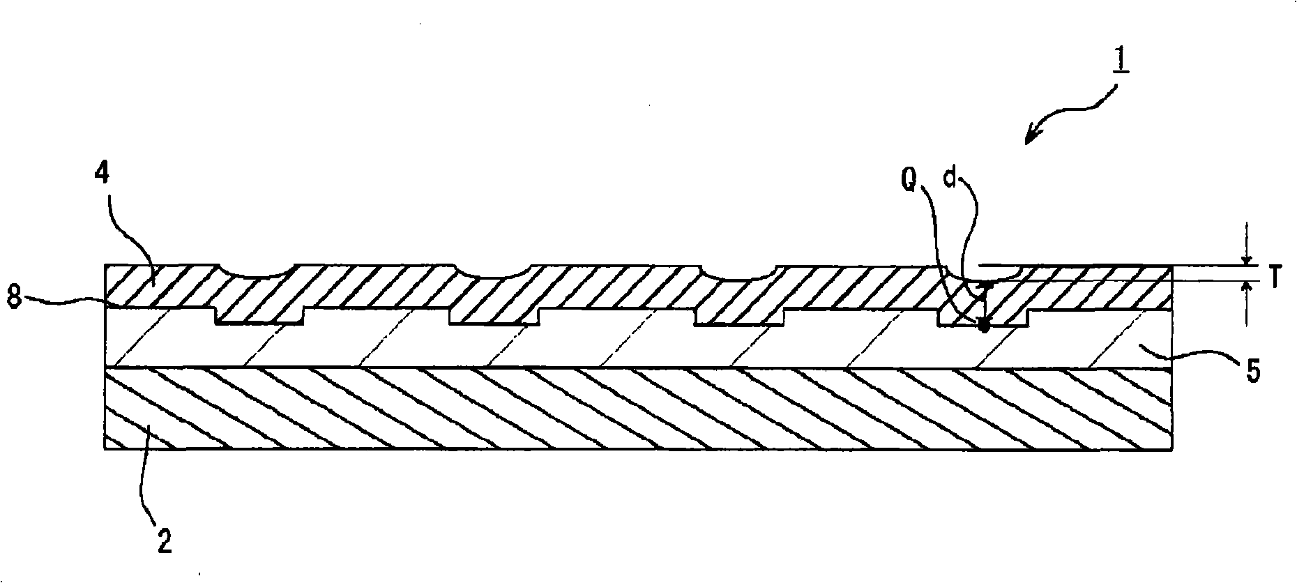
[0262] The film thickness (d) of the retardation layer in this retardation control member was 1.25 μm (125...
Embodiment 3
[0270] Prepare a glass substrate (manufactured by Corning Corporation, 1737 material) as a base material, and form a colored layer with a black matrix and a color pattern on the glass substrate as a bottom layer, except that, the same operation as in Example 1 is performed to obtain phase difference control member.
[0271] The colored layer was formed on the substrate as follows.
[0272] [Formation of colored layer]
[0273] First, in the same manner as in Example 1, a black matrix was formed on the surface of a glass substrate using a coloring material dispersion to obtain a glass substrate (BM forming substrate) on which a BM was formed.
[0274]
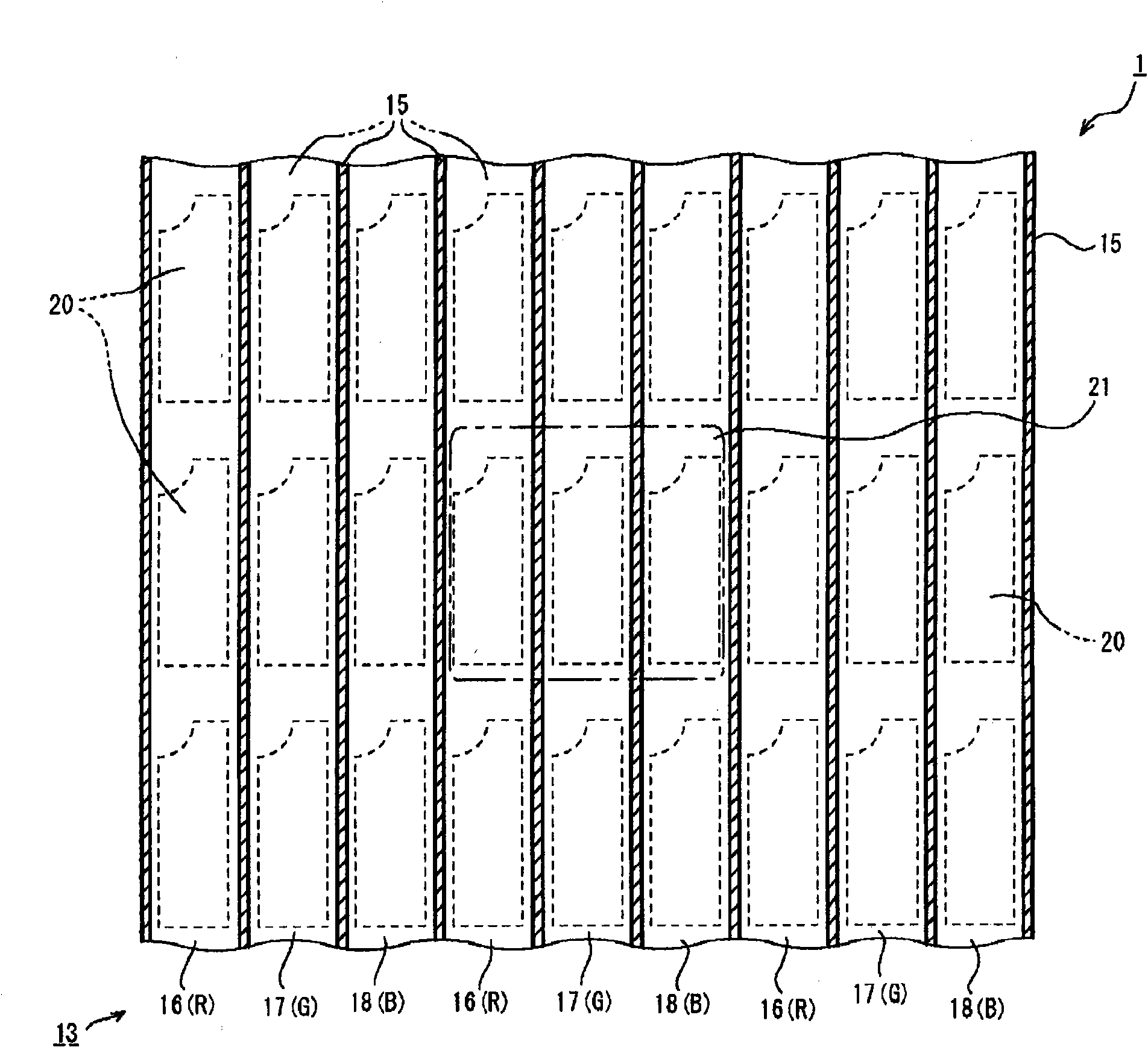
[0275] Coloring material dispersion liquids of red (R), green (G), and blue (B) color patterns were prepared. A pigment dispersion type photoresist can be used for the coloring material dispersion liquid of the color pattern of red (R), green (G), and blue (B).
[0276] The preparation of the pigment-dispersed photoresist o...
PUM
| Property | Measurement | Unit |
|---|---|---|
| thickness | aaaaa | aaaaa |
| thickness | aaaaa | aaaaa |
Abstract
Description
Claims
Application Information
 - Generate Ideas
- Intellectual Property
- Life Sciences
- Materials
- Tech Scout
- Unparalleled Data Quality
- Higher Quality Content
- 60% Fewer Hallucinations
Browse by: Latest US Patents, China's latest patents, Technical Efficacy Thesaurus, Application Domain, Technology Topic, Popular Technical Reports.
© 2025 PatSnap. All rights reserved.Legal|Privacy policy|Modern Slavery Act Transparency Statement|Sitemap|About US| Contact US: help@patsnap.com