Multicore communication cable comprehensive tester

The technology of a comprehensive tester and communication cable is applied in the field of multi-core communication cable comprehensive tester, which can solve the problems of increasing the workload of construction and maintenance, affecting the accuracy of measurement, and slowing down the work progress, so as to achieve high test reliability, Good anti-interference, easy to use on-site effect

Inactive Publication Date: 2010-08-11
姚晴洲 +1
View PDF0 Cites 25 Cited by
  • Summary
  • Abstract
  • Description
  • Claims
  • Application Information

AI Technical Summary

Problems solved by technology

[0002] In various connection and maintenance projects related to communication cables, construction and maintenance personnel often encounter problems caused by a large number of wires and cannot be distinguished when installing and repairing cables. At the same time, determine the type of cable fault and the fault The distance also increases the workload of construction and maintenance, slows down the work progress, and wastes a lot of manpower and material resources
At present, domestic related products are mainly limited to the fault point detection part. There is no manufacturer to develop and produce such comprehensive testing instruments. Such products sold in the domestic market are all imported from abroad, and the price is very expensive. Among them, the model developed and produced by German BEHA company is The market price of this kind of product of 9016 is 592 US dollars. This product mainly adopts the principle of resistive voltage division. Its disadvantage is that the resistance value is easily affected by external conditions and cable length, which affects the accuracy of measurement and has poor anti-interference performance.
In addition, since the divided voltage signal is a DC signal, it is difficult to expand the function, and in use, a reference ground wire with good conductivity must be introduced, which makes it unnecessary in long-distance cable detection and maintenance. Trouble

Method used


Image

  • Multicore communication cable comprehensive tester
  • Multicore communication cable comprehensive tester
  • Multicore communication cable comprehensive tester

Examples


Embodiment 1

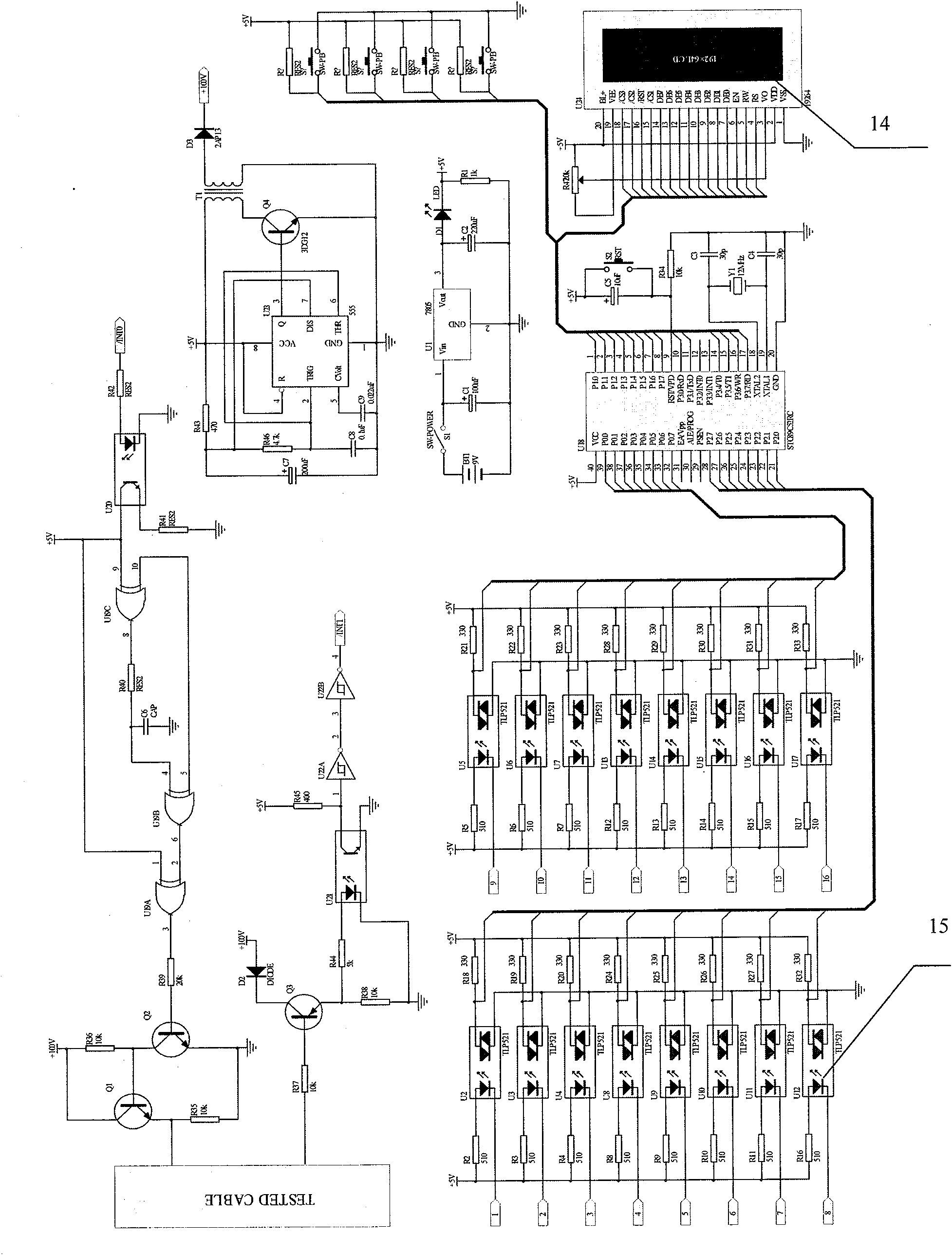
[0027] A cable comprehensive tester, its hardware mainly has two parts: a line sequence test signal transmitter 7 and a host 11, wherein the line sequence test signal transmitter includes a coded CPU8 and a coded sending circuit connected to the coded CPU8 and controlled by the coded CPU8 9. The host computer 11 includes several parts such as a decoding CPU 3, an encoding receiving circuit 5, a fault point ranging signal transmitting / receiving circuit 1, a display 2, and a keyboard 4. The encoding receiving circuit 5 and the fault point ranging signal transmitting / receiving circuit 1. The display 2 and the keyboard 4 are respectively connected to the decoding CPU3 and controlled by the decoding CPU3. The encoding receiving circuit 5 adopts a low-speed AD chip 14, and the encoding transmitting circuit 9 and the encoding receiving circuit 5 are provided with an optocoupler 15 Isolated from the cable 6 to be tested.

[0028] The peripheral interface of the wire sequence test sign...


PUM


Abstract

The invention relates to a multicore communication cable comprehensive tester. The tester comprises a line-sequential test signal transmitter and a host. The tester is characterized in that the line-sequential test signal transmitter comprises a coding CPU and a code-sending circuit which is connected with the coding CPU and controlled by the coding CPU; the host comprises a decoding CPU, a code-receiving circuit, a fault range-finding signal transmitting / receiving circuit, a monitor and a keyboard; and the code-receiving circuit, the fault range-finding signal transmitting / receiving circuit, the monitor and the keyboard are separately connected with the decoding CPU, the code-receiving circuit adopts a low-speed AD chip, and the code-receiving circuit and the code-receiving circuit are provided with optocouplers which are separated from a cable to be tested. The tester of the invention has simple structure, low cost, high reliability and high anti-interference performance, and can be used to test long cables and be applicable to the connection and maintenance projects of various cables.

Description

technical field [0001] The invention relates to a cable testing device, in particular to a multi-core communication cable comprehensive tester which can simultaneously locate and mark both ends of a long-distance multi-core communication cable one by one and detect cable fault types and fault locations. Background technique [0002] In various connection and maintenance projects related to communication cables, construction and maintenance personnel often encounter problems caused by a large number of wires and cannot be distinguished when installing and repairing cables, and at the same time determine the type of cable fault and the fault The distance also increases the workload of construction and maintenance, slows down the work progress, and wastes a lot of manpower and material resources. At present, domestic related products are mainly limited to the fault point detection part. There is no manufacturer to develop and produce such comprehensive testing instruments. Such...

Claims


Application Information

Patent Timeline
IPC IPC(8): G01R31/11
Inventor 姚晴洲周志青
Owner 姚晴洲
Why Eureka
Try Eureka