Display control device and control method thereof

A display control and display device technology, applied to static indicators, instruments, televisions, etc., can solve the problem of excessive display device time

Active Publication Date: 2010-08-04
CANON KK
View PDF6 Cites 10 Cited by
  • Summary
  • Abstract
  • Description
  • Claims
  • Application Information

AI Technical Summary

Problems solved by technology

However, in this case, for example, there arises a defect that it takes too much time for the luminance of the display device to reach the optimum level when the illuminance of external light changes.

Method used


Image

  • Display control device and control method thereof
  • Display control device and control method thereof
  • Display control device and control method thereof

Examples


no. 1 example

[0029] The display control device according to the first embodiment of the present invention is applied to a digital single-lens reflex camera (SLR), but can also be applied to other digital cameras such as compact cameras and video cameras.

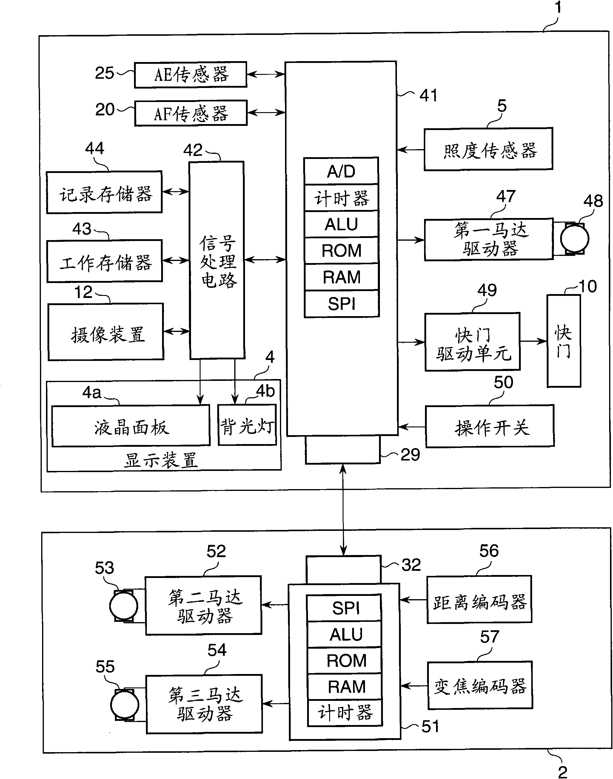
[0030] figure 1 The circuit configuration of a digital camera including the display control device of this embodiment is shown in a block diagram. This digital camera includes a camera main unit 1 and an interchangeable lens 2 .

[0031] The camera main unit 1 includes a single chip (control unit) 41 including, for example, ALU, ROM, RAM, A / D converter, timer, and serial communication port (SPI), and performs overall control of, for example, the camera mechanism. The control performed by the control unit 41 will be described in detail later.

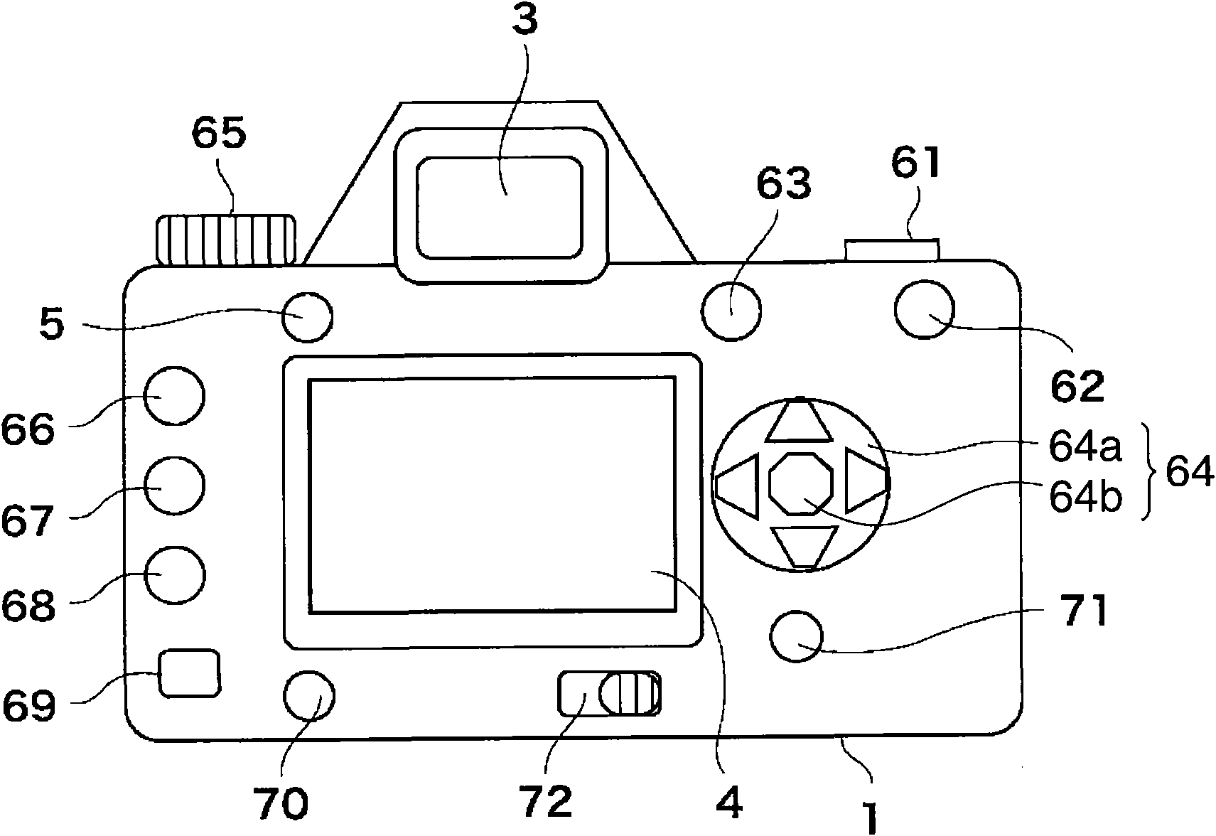
[0032] The display device 4 mounted to the camera main unit 1 is realized by, for example, a liquid crystal display monitor having a liquid crystal panel 4 a and a backlight 4 b. The illuminance...


PUM


Abstract

A display control device capable of suppressing an abrupt change in brightness of a display device viewed by a user when a large change takes place in outside light illuminance, thereby relieving a viewing difficulty. A control unit detects illuminance of outside light irradiated onto the display device, calculates a target brightness value corresponding to the detected illuminance, and sets a brightness setting value for the display device based on the target brightness value. If there is continuity in display content of the display device, the brightness setting value is set while providingan upper limit value for an amount of change in target brightness value. If the display content is changed without continuity, the target brightness value is set as the brightness setting value whileunrestricting the amount of change in the target brightness value.

Description

technical field [0001] The present invention relates to a display control device for controlling a display device for displaying images, and a method for controlling the display control device. Background technique [0002] Conventionally, most digital cameras for recording and displaying an electronic image photoelectrically converted by an imaging device have a display device for displaying the recorded image and information necessary for shooting. [0003] As a display device, a TFT liquid crystal display device is generally used, but an organic EL display device or the like may be used in some cases. [0004] There are three types of TFT liquid crystal display devices, ie, transmissive, reflective, and semi-transmissive. In order to display an image recorded by a digital camera, a transmissive display device excellent in image display performance (eg, contrast and color reproduction) but requiring a backlight is mostly used. Thus, a transmissive display device includes...

Claims


Application Information

Patent Timeline
Patent Type & Authority Applications(China)
IPC IPC(8): G09G3/20G09G3/36H04N5/225
CPCG09G3/32H04N5/23209G09G3/3406G09G3/20H04N5/2353H04N5/23212G09G2320/0626G09G3/28G09G2320/0606G09G2360/144H04N23/663H04N23/672H04N23/633H04N23/632H04N23/73
Inventor 大泽敏文
Owner CANON KK
Why Eureka
Try Eureka