
Symmetrical toggle rod pressure transmission mechanism

A technology of transmission mechanism and toggle lever, applied in the direction of presses, punching machines, transmission devices, etc., can solve the problems of low work efficiency, reduce motor driving torque, occupy high space, etc., achieve high positioning and repeated positioning accuracy, and improve work efficiency. Efficiency, the effect of improving transmission efficiency

Inactive Publication Date: 2010-07-28
HUAZHONG UNIV OF SCI & TECH
View PDF5 Cites 16 Cited by
  • Summary
  • Abstract
  • Description
  • Claims
  • Application Information

AI Technical Summary

Problems solved by technology

2. The force-increasing function of the symmetrical six-bar linkage mechanism is more obvious, which reduces the driving torque of the motor
However, the transmission mechanism of the symmetrical six-link press has the following problems: 1. The height of the frame is large, which occupies a high space and requires a tall delivery room, thus increasing the construction cost of the plant; 2. The speed of the empty stroke is slow, resulting in work efficiency 3. The effective boosting stroke is short, resulting in a short working range of the mechanism

Method used


Image

  • Symmetrical toggle rod pressure transmission mechanism
  • Symmetrical toggle rod pressure transmission mechanism
  • Symmetrical toggle rod pressure transmission mechanism

Examples


Embodiment 1

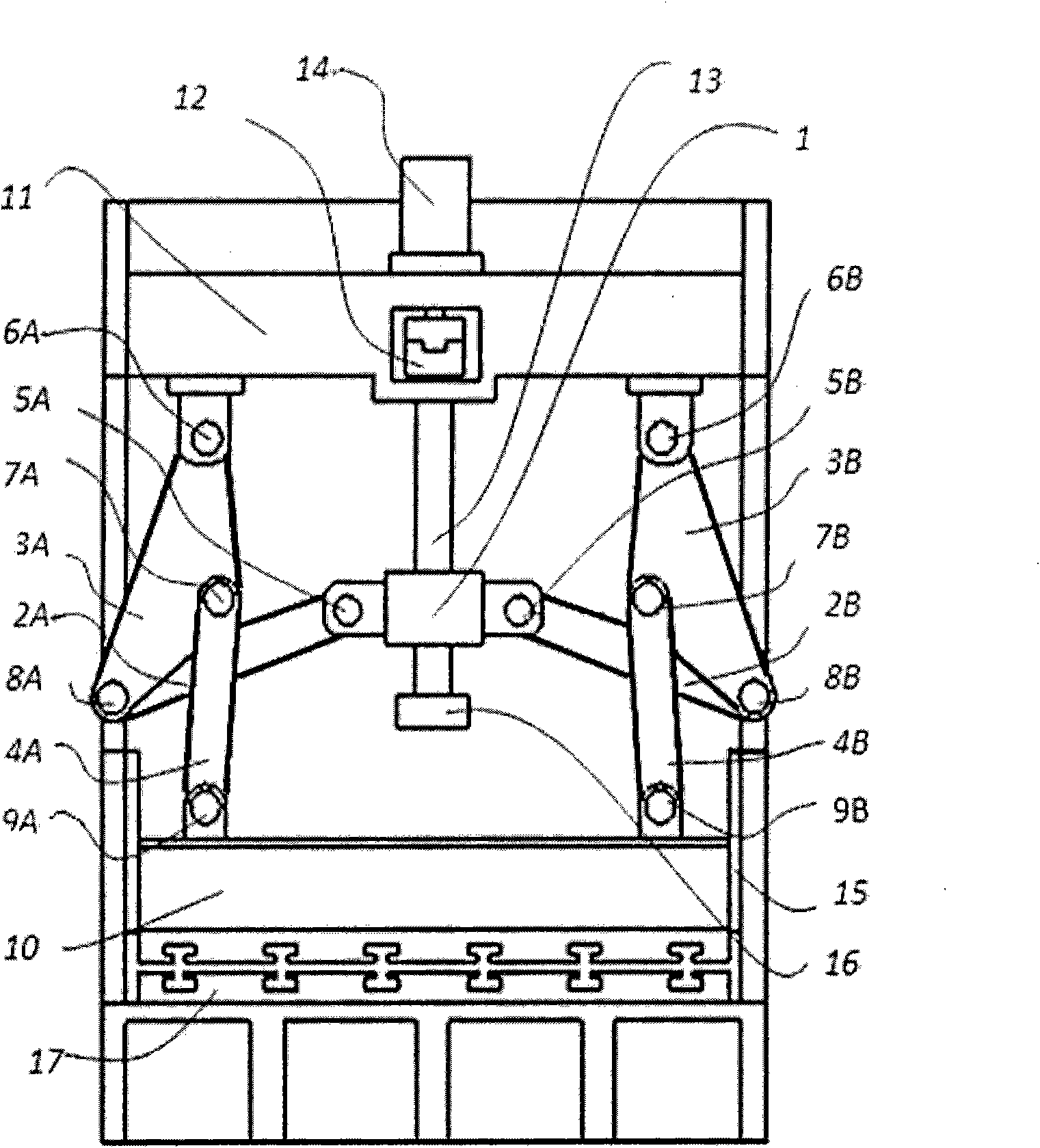
[0027] Such as figure 1 As shown, the first upper toggle plate 3A is fixed with the first upper beam hinge 6A, the first toggle hinge 7A and the first connecting hinge 8A, and the first upper toggle plate 3A is connected to the frame 11 through the first upper beam hinge 6A One end of the first lower toggle 4A is connected to the first upper toggle plate 3A through the first toggle hinge 7A, and the other end of the first lower toggle 4A is connected to the slider 10 through the first slider hinge 9A; the first intermediate link One end of 2A is connected to the first upper toggle plate 3A through the first connecting hinge 8A, and the other end of the first intermediate link 2A ​​is connected to the driving block 1 through the first driving hinge 5A.

[0028] Symmetrically, the second upper toggle plate 3B is fixed with a second upper beam hinge 6B, a second toggle hinge 7B and a second connecting hinge 8B, and the second upper toggle plate 3B is connected to the frame 11 thr...

Embodiment 2

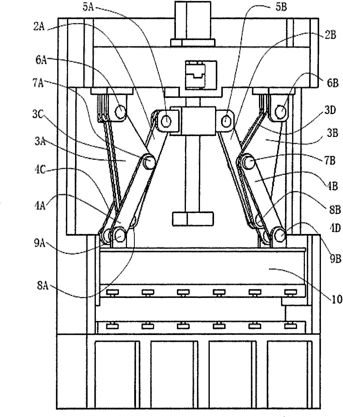
[0038] In order to ensure the force balance and stable operation of the mechanism, the respective numbers of the upper toggle plate, the lower toggle link and the intermediate link in the toggle mechanism can be arbitrarily determined according to actual needs without interference. In this embodiment, the single toggle mechanism has 2 upper toggle plates, 2 lower toggles, and 1 intermediate link.

[0039] Such as figure 2As shown, the third upper toggle 3C, the third lower toggle 4C, the fourth upper toggle 3D, and the fourth lower toggle 4D are added to the mechanism respectively with the first upper toggle 3A, the first lower toggle 4A, The second upper toggle plate 3B and the second lower toggle lever 4B form a group corresponding to the front and rear. Specifically, the arrangement is as follows: the first intermediate link 2A ​​is hinged with the first upper toggle plate 3A and the third upper toggle plate 3C through the first connecting hinge 8A, and the third lower to...

Embodiment 3

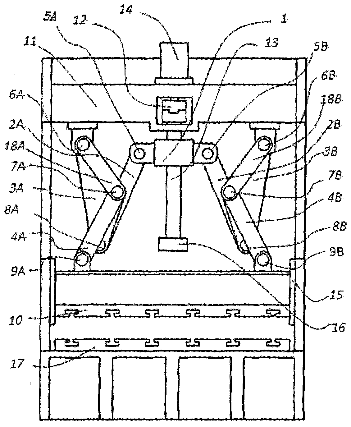
[0042] Such as image 3 As shown, in this embodiment, in order to have better mechanical properties of the mechanism, the first auxiliary upper bracket 18A, the second auxiliary upper bracket 18B, and the third auxiliary upper bracket 18C are added on the basis of the second embodiment. The fourth auxiliary upper toggle plate 18D is specifically arranged as follows: the first auxiliary upper toggle plate 18A and the second auxiliary upper toggle plate 18B are respectively added on the front side of the first lower toggle lever 4A and the second lower toggle lever 4B, A third auxiliary upper toggle plate 18C and a fourth auxiliary upper toggle plate 18D (not shown in this figure) are respectively added to the rear side of the lower toggle link 4C and the fourth lower toggle link 4D, and one end of the first auxiliary upper toggle plate 18A The first upper beam hinge 6A is hinged to the frame 11, the other end is hinged to the first lower toggle 4A through the first toggle hinge...


PUM


Abstract

The invention relates to a symmetrical toggle rod pressure transmission mechanism belonging to the field of connecting bar transmission mechanisms. The toggle rod pressure transmission mechanism comprises toggle rod mechanisms, a drive block, a slide block and a rack, wherein two toggle rod mechanisms are symmetrically arranged at both sides of an axis of a drive rod positioned in the center of the mechanism; each toggle rod mechanism comprises an upper toggle plate, a lower toggle rod and a middle connecting bar, wherein the upper toggle plate is respectively connected with the lower toggle rod, the middle connecting bar and the rack through a toggle rod hinge, a connection hinge and an upper beam hinge, the other end of the lower toggle rod is connected with the slice block through a slide block hinge, and the other end of the middle connecting bar is connected with a driving slide block through a driving hinge; and a segment taking the axle centers of the two connection hinges as endpoints is always intersected with a straight line passing through the axle center of the upper beam hinge and the axle center of the toggle rod hinge positioned at the same side with the upper beam hinge. Compared with the traditional symmetrical six-bar mechanism, the invention has good force-increasing effect, relative uncomplicated stress of a load-bearing shaft, difficult breakage, low total height of the mechanism, and the like.

Description

technical field [0001] The invention belongs to a connecting rod transmission mechanism, in particular to a pressure transmission mechanism. Background technique [0002] Symmetrical six-bar linkage press (product of Amino (Wuhan) High-Tech Co., Ltd.) is a newly popular plastic processing equipment. Compared with other traditional press mechanisms, such as the crank-connecting rod transmission press (see "<crank press", He Deyu, Machinery Industry Press, 1987), the toggle transmission press (see "Mechanical Press Knuckle Press") Optimum Design of Rod Transmission Mechanism", Zhang Yuantong, Zhu Denglin, "Machinery and Electronics", 2008(1), pp. 10-12), hydraulic transmission press (see "Design and Application of Hydraulic Press", Yu Xinlu, Machinery Industry Publishing House) and screw drive presses (see J58K series CNC electric screw presses of Wuhan Xinweiqi Technology Co., Ltd.) have certain advantages. It is reflected in: 1. The lateral force of the slider is equal ...

Claims


Application Information

Patent Timeline
IPC IPC(8): F16H21/00B30B1/10
CPCB30B1/106
Inventor 莫健华杨昊玥
Owner HUAZHONG UNIV OF SCI & TECH
Learn More