
Method for adjusting roll axial direction of multi-diagonal roll straightener

A technology of axial adjustment and straightening machine, applied in the direction of metal rolling stand, metal rolling mill stand, metal rolling, etc., can solve the problems of inability to fix, overturn, and heavy upper roll device.

Inactive Publication Date: 2010-07-28
CITIC HEAVY INDUSTRIES CO LTD +1
View PDF6 Cites 4 Cited by
  • Summary
  • Abstract
  • Description
  • Claims
  • Application Information

AI Technical Summary

Problems solved by technology

In my country's metallurgical production enterprises, the axial adjustment device of the straightening roller has the following deficiencies in use: 1. Since the upper roller device is very heavy, two support devices are required for axial adjustment, and the upper roller device is generally lifted by a jack. However, due to limited space, the supporting device cannot support the center of gravity of the upper roller device and cannot be fixed itself, which makes it difficult to adjust the upper roller device
2. When the bearing seat is moved horizontally and axially, the supporting device will tilt and fall with the movement of the bearing seat, causing the bearing seat to tilt and causing uneven force on the bolts connected to the turntable
After the adjustment is in place, it is very difficult to tighten the connecting bolts, and it is difficult to ensure good contact between the bottom surface of the bearing seat and the plane of the turntable, which will cause vibration when the straightener is working and affect the straightening accuracy
3. When the bearing seat is moved horizontally and axially, the two bearing seats move asynchronously, which increases the difficulty of adjustment

Method used


Image

  • Method for adjusting roll axial direction of multi-diagonal roll straightener
  • Method for adjusting roll axial direction of multi-diagonal roll straightener
  • Method for adjusting roll axial direction of multi-diagonal roll straightener

Examples


Embodiment Construction

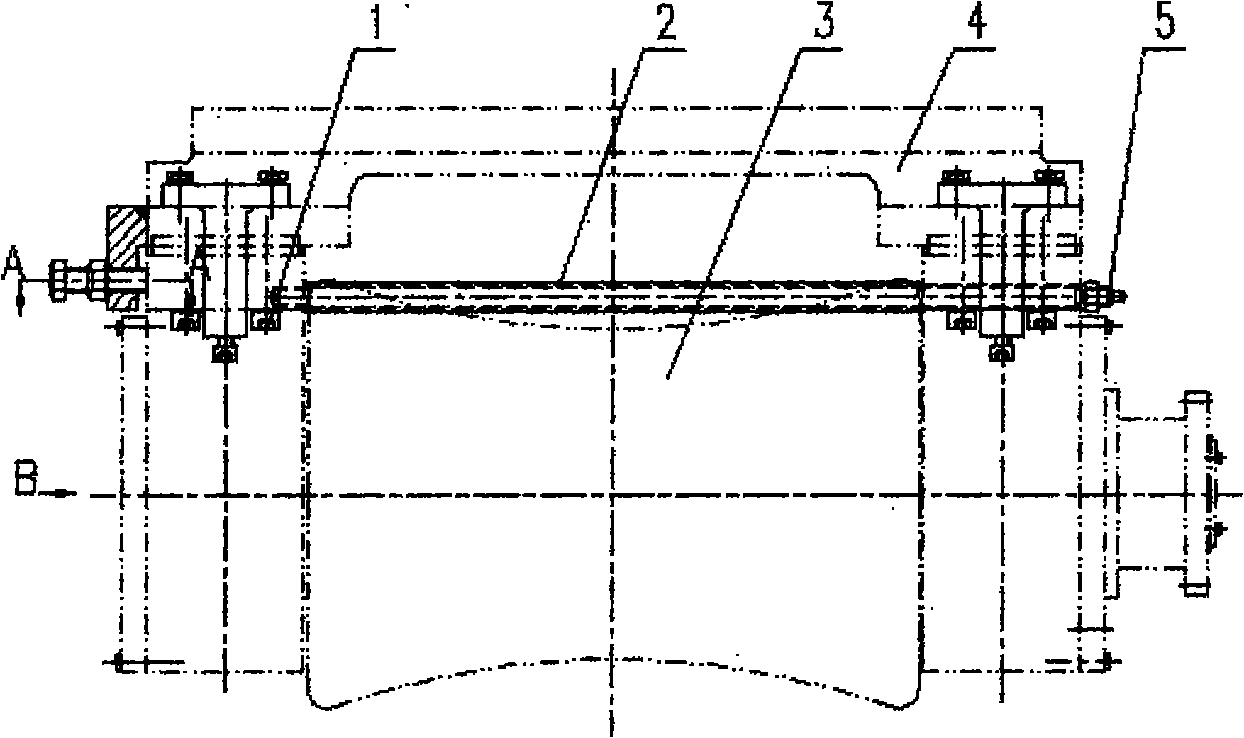
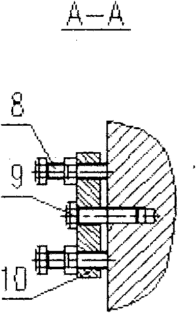
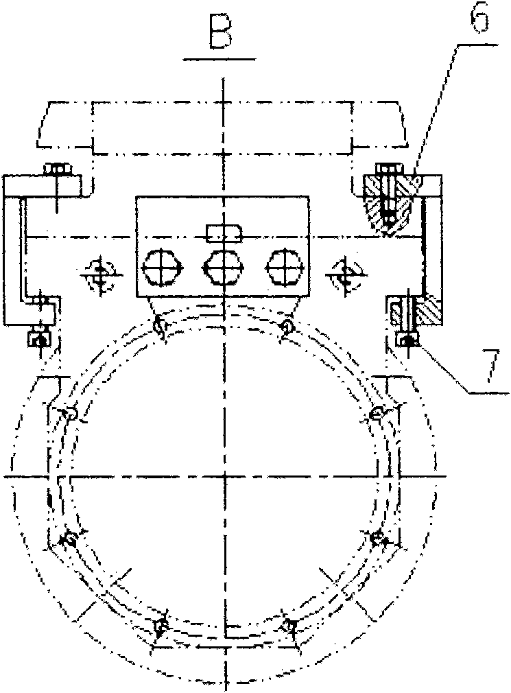
[0016] Such as figure 1 , 2 , shown in 3: a method for axial adjustment of the upper roller of a multi-skewed roller leveler, the adjustment device of the upper straightening roller of the leveler is set to an axial adjustment form and a lateral fixed and vertical adjustment form, and the axial adjustment form The end surface of the axial adjustment bolt bracket is provided with an axial adjustment bolt for adjusting the axial direction of the upper straightening roller device. The side of the turntable of the straight roller device; the lateral fixation and vertical adjustment form, the upper and lower ends of the C-shaped frame are provided with vertical adjustment bolts to withstand the bearing seat; the C-shaped frame and the turntable of the upper straightening roller device are fixed Fixed, stuck on the outer edge of the bearing seat and the turntable. The axial adjustment device of the upper roll of the straightening machine consists of a bolt (1), a distance tube (2)...


PUM


Abstract

The invention discloses a method for adjusting the roll axial direction of a multi-diagonal roll straightener, and an upper straightening roll adjusting device of the straightener is set into an axial adjusting mode and a sidewise fixing and vertical adjusting mode. The method comprises the following steps: a, before an axial adjustable bearing seat moves, propping the bearing seat by adjusting a vertical adjustable bolt (7) on a C-shaped bracket; b, loosening the bolt (1) connecting the bearing seat and a turnplate (6); c, realizing axial adjustment of the upper straightening roll device respectively by an axial adjustable bolt A (8) and an axial adjustable bolt B (9) when the adjustable bearing seat moves axially; and d, tightening the bolt connecting the bearing seat and the turnplate (6) firmly when adjustment is in place. The invention has convenient adjustment operation and assembly and disassembly of an upper roll device, can ensure good contact of the bearing seat bottom surface and the turnplate surface so as to avoid straightening precision from being influenced by shock produced in the working process of the straightener, leads the two bearing seats to work synchronously, and has reliable operation and strong market competitiveness and promotion value.

Description

technical field [0001] The invention relates to the technical field of straightening machines, in particular to a method for adjusting the axial direction of upper rollers of a multi-skewing-roller straightening machine for tubes and bars. technical background [0002] At present, the axial adjustment device is mainly used in pipe and bar straightening machines in the metallurgical industry. The main function is to ensure the centering and concentricity of multiple straightening rollers. During the straightening process, the round material passes through multiple pairs of staggered straightening rollers in sequence. The adjustment of the straightening rollers directly affects the relationship between the round material and the straightening rollers during straightening. Contact conditions have a direct impact on product quality. In my country's metallurgical production enterprises, the axial adjustment device of the straightening roller has the following deficiencies in use...

Claims


Application Information

Patent Timeline
Patent Type & Authority Applications(China)
IPC IPC(8): B21D3/04B21B31/18
Inventor 王孟德左会峰王希霞张明灿张莉刘治乾
Owner CITIC HEAVY INDUSTRIES CO LTD
Learn More