
Sensor for TDR soil moisture measuring instrument based on phase detection principle

A soil moisture and phase detection technology, applied in the field of measurement, can solve problems such as the difficulty of incident-reflection time difference and the high cost of measurement equipment, and achieve the effect of reducing reflection and improving measurement accuracy

Inactive Publication Date: 2010-07-21
CHINA AGRI UNIV
View PDF3 Cites 14 Cited by
  • Summary
  • Abstract
  • Description
  • Claims
  • Application Information

AI Technical Summary

Problems solved by technology

[0009] The technical problem to be solved by the present invention is to overcome the defect that the above-mentioned incident-reflection time difference in the existing TDR soil moisture measurement technology is difficult to accurately measure the high cost of the measuring equipment, and reduce the total cost of the measuring instrument while improving the measurement accuracy

Method used


Image

  • Sensor for TDR soil moisture measuring instrument based on phase detection principle
  • Sensor for TDR soil moisture measuring instrument based on phase detection principle
  • Sensor for TDR soil moisture measuring instrument based on phase detection principle

Examples


Embodiment Construction

[0024] The sensor proposed by the present invention for the TDR soil moisture measuring instrument based on the principle of phase detection is described as follows in conjunction with the accompanying drawings and embodiments.

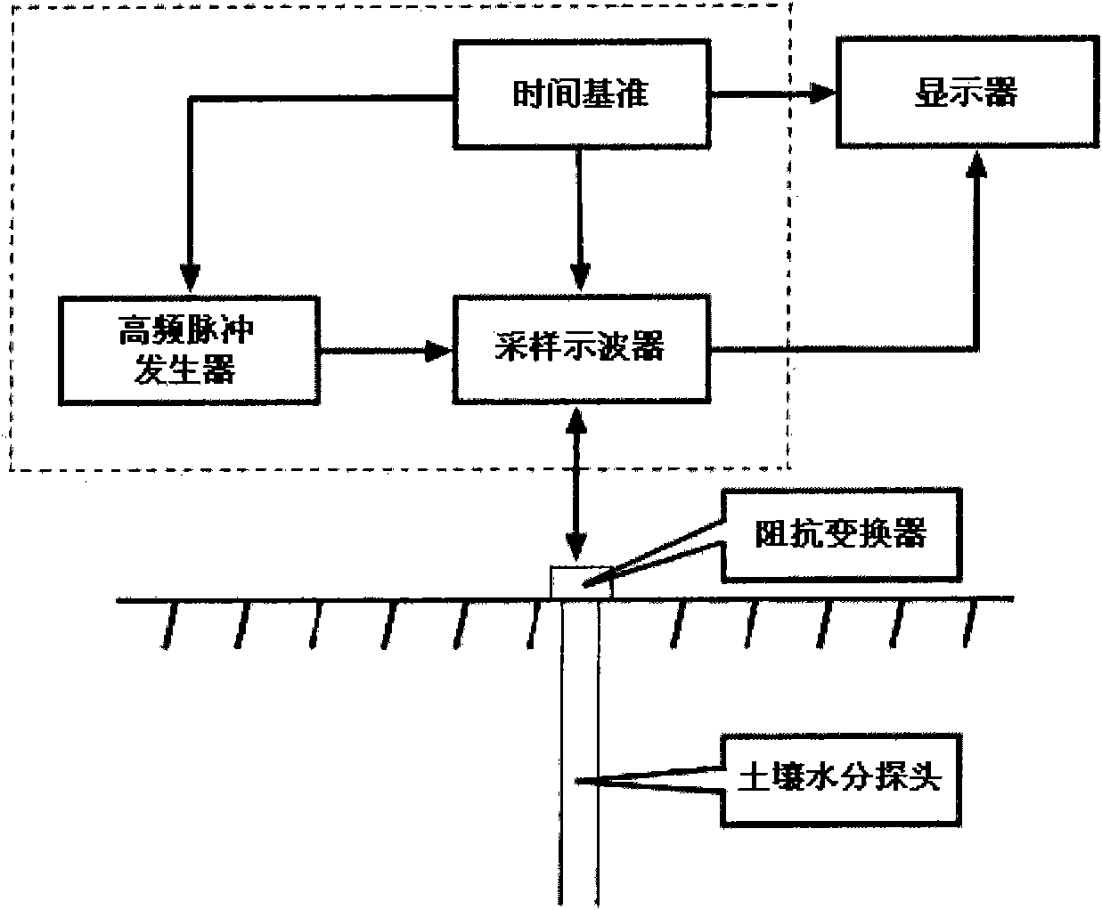
[0025] In order to make the principle of the present invention clearer, it is first necessary to briefly introduce the TDR soil moisture measuring instrument (P-TDR) based on the phase detection principle used in conjunction with the accompanying drawings.

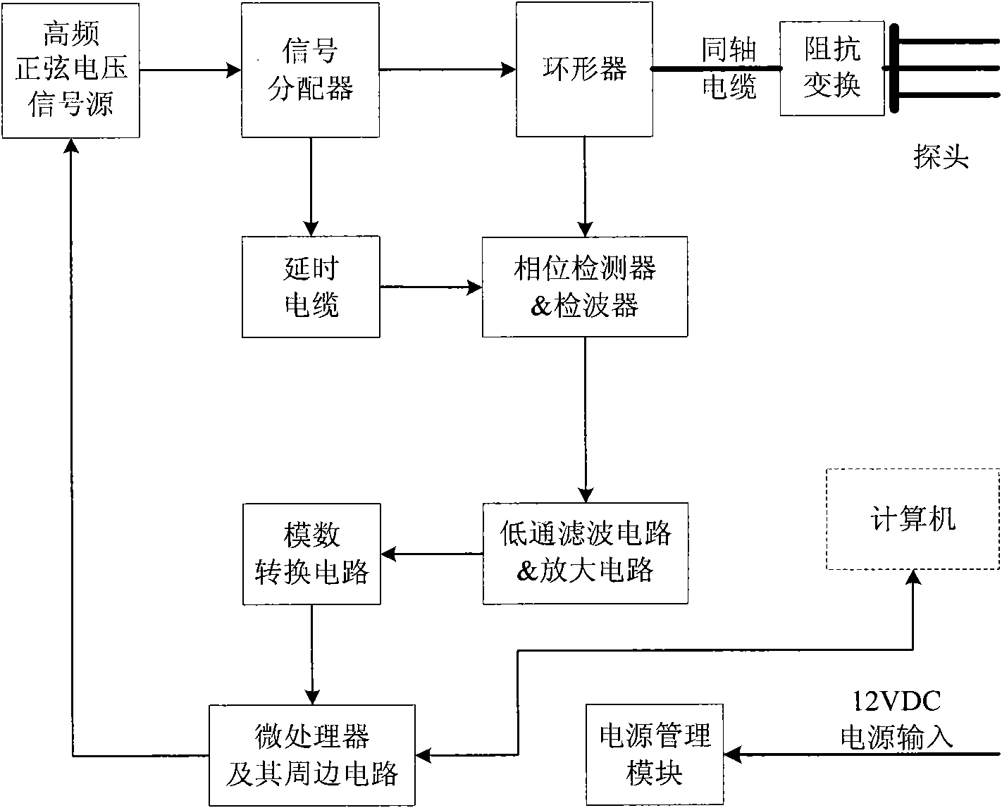
[0026] Such as figure 2 As shown in , the TDR soil moisture measuring instrument (P-TDR) based on the principle of phase detection includes: a signal source, which is used to generate a high-frequency sine wave voltage signal, and the frequency of the output signal is adjustable between 320MHz and 480MHz; signal distribution The device is used to transmit the signal output by the signal source to the circulator and the delay cable respectively; the delay cable is used to delay the transmission of...


PUM

PropertyMeasurementUnit
Thicknessaaaaaaaaaa
Lengthaaaaaaaaaa
Diameteraaaaaaaaaa

Abstract

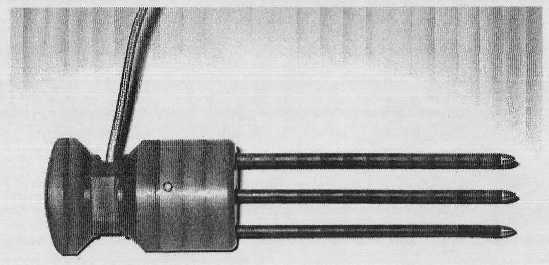
The invention provides a sensor for a TDR soil moisture measuring instrument based on a phase detection principle. The invention is characterized in that the sensor comprises a shell and three metal probes; a coaxial cable is led out from the inside of the shell and is connected with the main body of the TDR soil moisture measuring instrument based on the phase detection principle; and the three metal probes are arranged at the lower end of the shell in parallel, the surface of each metal probe is covered by a PVC insulating layer and the head end of each metal probe is inlaid into the shell and is connected with the coaxial cable. The sensor for the P-TDR soil moisture measuring instrument is connected with a P-TDR host computer through an impedance transformer and the coaxial cable; and since the each metal probe is covered by the PVC coating to enable the characteristic impedance of the probes in soil to be matched with the coaxial cable, the signal reflection at the head end of the probe is reduced and the measurement accuracy is further improved.

Description

technical field [0001] The invention relates to the field of measurement technology, in particular to a sensor that can be installed on the main body of a time domain reflectance (TDR) soil moisture meter, especially a time domain reflectance soil moisture meter (P-TDR) based on the principle of phase detection. Background technique [0002] In 1975, Davis and Chudobiak applied time domain reflectometry (TDR) to the determination of soil dielectric constant. In 1980, when Topp et al. used TDR to measure the dielectric constant of soil, they proved that the dielectric constant had a good correlation with soil water content, and established an empirical formula between soil water content and apparent dielectric constant. Compared with other methods, TDR has many advantages in soil moisture measurement, such as non-destructive, fast, high accuracy, measurement results are less affected by soil type, and can simultaneously measure soil moisture content and soil electrical conduc...

Claims


Application Information

Patent Timeline
IPC IPC(8): G01N22/04
Inventor 王一鸣龚元石王克栋张方贤李子忠杨卫中冯磊董乔雪李信洪
Owner CHINA AGRI UNIV
Learn More