
Complex heat-preservation roof and construction method thereof

A composite thermal insulation and roofing technology applied in the field of building components to achieve the effects of easy operation, simple process and simple structure

Active Publication Date: 2013-01-09
谭齐阳
View PDF0 Cites 0 Cited by
  • Summary
  • Abstract
  • Description
  • Claims
  • Application Information

AI Technical Summary

Problems solved by technology

[0003] However, in existing buildings, few roofs are made for insulation and ventilation

Method used


Image

  • Complex heat-preservation roof and construction method thereof
  • Complex heat-preservation roof and construction method thereof
  • Complex heat-preservation roof and construction method thereof

Examples


Embodiment 1

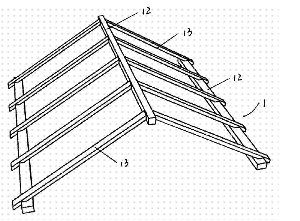
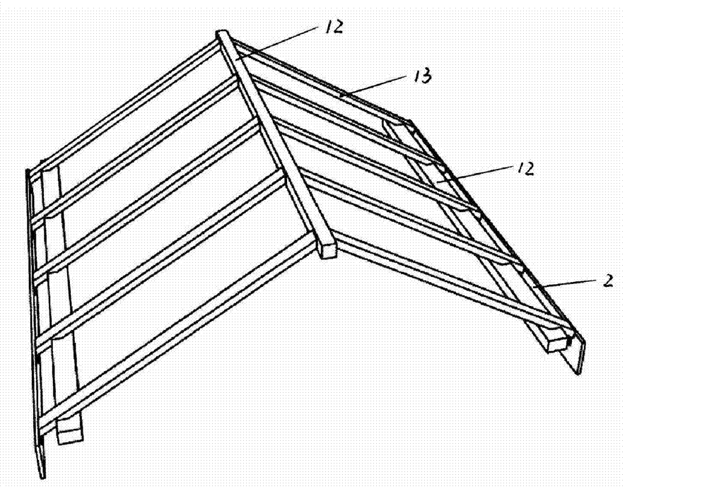
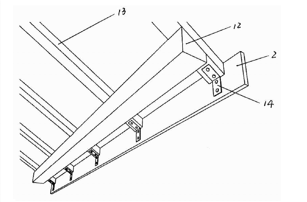
[0041] The present invention includes roof frame 1, EPS board (polystyrene board) 3 and waterproof board 5. The cross section of roof frame 1 is triangular and consists of three horizontal ribs 12 and multiple longitudinal ribs 13. The triangles are respectively arranged on three vertices, and a plurality of longitudinal ribs 13 are respectively arranged between the transverse rib at the highest point and the other two transverse ribs at the lower position; one end of the longitudinal rib 13 is fixed at the highest transverse rib On both sides of the ribs, the other end is fixed on the lower horizontal ribs and extends a certain distance outward. The extended distance can be determined according to the design drawings. An EPS board 3 is provided between two adjacent longitudinal ribs 13, the upper surface of the EPS board is coplanar with the upper surface of the longitudinal ribs; a reflective film 4 is pasted on the EPS board 3 and the longitudinal ribs 13, reflecting A water...

Embodiment 2

[0046] The difference between this embodiment and the first embodiment is that the thickness of the EPS board 3 is smaller than the thickness of the longitudinal ribs 13, and the upper surface of the EPS board installed between the longitudinal ribs is lower than the upper surface of the longitudinal ribs; The ribs 13 can be in the shape of "I" or square. When the longitudinal ribs 13 are in the shape of "I", the EPS board 3 is installed in the groove of the shape of "I". Support beams can be arranged between the longitudinal ribs, and the EPS board is installed on the support beams. Due to the height difference between the EPS board and the longitudinal ribs, after the waterproof board is installed on the longitudinal ribs, there will be a gap for exhaust air between the waterproof board and the reflective film on each EPS board. In addition, on the two sides near the top of the roof and above the EPS boards with reflective films, horizontal ribs 12 are respectively added, and...


PUM


Abstract

The invention relates to a building member, in particular to a complex heat-preservation roof and a construction method thereof. The roof comprises a roof truss, EPS boards and waterproof boards, the multiple EPS boards are arranged between purlins of the roof truss, and the waterproof boards are arranged on the EPS boards and the purlins; and the two end surfaces of the roof truss are also provided with the waterproof boards. The construction method is as follows: the EPS boards are arranged on the roof truss, the upper surface of each EPS board and the upper surfaces of the purlins are coplanar; reflecting films are stuck on the upper surfaces of the purlins and the EPS boards; the waterproof boards are assembled on the two sides of the lowest end of the roof truss, and then are paved on the previous layer until the surface of the roof truss is completely paved; a baffle is arranged on the roof truss and is provided with a first bracket, the first bracket is provided with an external pinchplate, and a drain tank is arranged on the first bracket by the external pinchplate; a second bracket is arranged below the first bracket, and a perforated plate is arranged on the second bracket; and the waterproof boards are used to seal the two end surfaces o the roof truss. The invention has the advantages of environment protection, heat preservation, thermal insulation, sound insulation, convenient installation and the like.

Description

Technical field [0001] The invention relates to building components, in particular to a composite thermal insulation roof and a construction method thereof. Background technique [0002] At present, in the construction industry, more and more attention is paid to the issue of building insulation. For a good insulation building, not only the wall insulation, but also the insulation of doors, windows, and roofs must be considered. Only in this way can it be called an insulation building and the building can achieve energy savings of more than 65%. At the same time, when the building energy saving reaches 65% or more, the indoor ventilation problem must be considered. Only in this way can the indoor humidity be controlled between 35% and 45%, and it will become a systematically complete energy-saving building. [0003] However, in existing buildings, very few roofs are used for insulation and ventilation. How to make the roof of a building both heat preservation and ventilation has ...

Claims


Application Information

Patent Timeline
Patent Type & Authority Patents(China)
IPC IPC(8): E04B7/02E04D3/00E04D11/00
Inventor 谭齐阳
Owner 谭齐阳
Learn More