
Yarn winding device and spinning machine

A technology of winding device and filament, which is used in transportation and packaging, transportation of filamentous materials, and processing of thin materials, etc., which can solve the problems of inability to form packages.

Active Publication Date: 2010-07-21
TMT MACHINERY INC
View PDF2 Cites 10 Cited by
  • Summary
  • Abstract
  • Description
  • Claims
  • Application Information

AI Technical Summary

Problems solved by technology

In addition, due to the deviation of the relative positional relationship, the structure disclosed in the above-mentioned Patent Document 1 may not be able to form the package at the desired position of each winding bobbin.

Method used


Image

  • Yarn winding device and spinning machine
  • Yarn winding device and spinning machine
  • Yarn winding device and spinning machine

Examples


Embodiment Construction

[0038] Refer below Figure 1-7 The first aspect of the present application will be described.

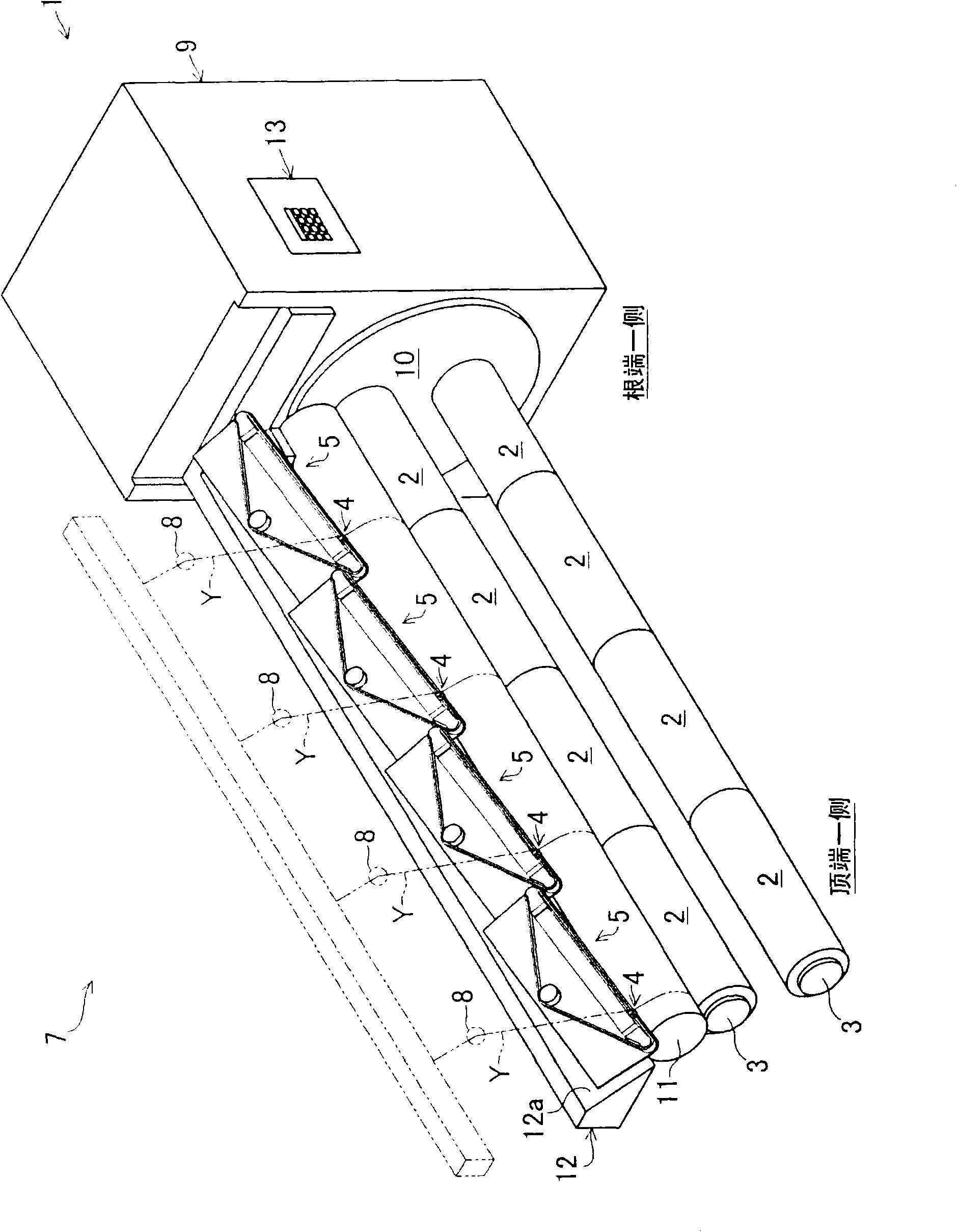
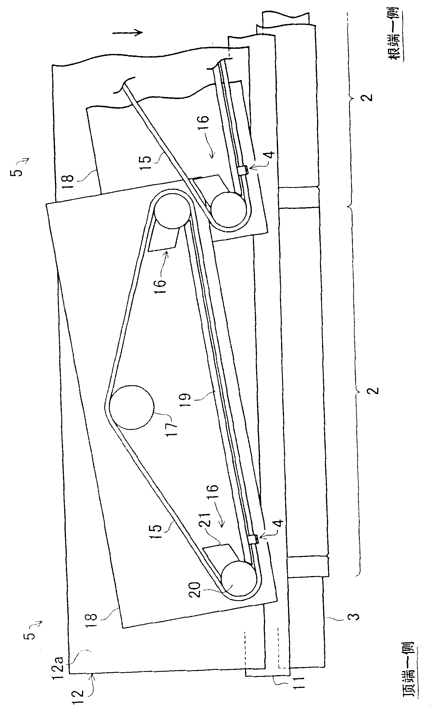
[0039] figure 1 It is a perspective view of the yarn winding device according to the first embodiment of the present invention. like figure 1 As shown, the yarn winding device 1 of this embodiment has a bobbin holder 3 and a plurality of (4 in this embodiment) traverse devices 5 as a main structure, and the bobbin holder 3 is rotated from one direction on the same axis. There are a plurality of (4 in this embodiment) winding bobbins 2 that are used to wind respectively provided multiple (4 in this embodiment) filaments Y that are arranged next to each other; the traverse device 5 has The yarn guide 4 capable of catching each of the above-mentioned yarns Y traverses each yarn Y with respect to each winding bobbin 2 by reciprocating the yarn guide 4 . In addition, each traverse device 5 has a structure in which the reciprocating range of each yarn guide 4 is shifted in the longi...


PUM


Abstract

The present invention provides a yarn winding apparatus which, even when the relative positional relationship between each take-up tube and the corresponding traverse device is deteriorated, enables a package to be formed at the desired position with respect to the corresponding take-up tube. A yarn winding apparatus 1 includes a bobbin holder 3 on which a plurality of take-up tubes 2 are installed and supported on the same shaft, and a plurality of traverse devices 5 each including a yarn guide 4 and configured to reciprocate the yarn guide 4 to traverse a yarn Y with respect to a corresponding take-up tube 2. Each of the traverse devices 5 allows a reciprocating range of reciprocation of the yarn guide 4 to be varied and is located in association with the corresponding take-up tube 2.

Description

technical field [0001] The invention relates to a yarn winding device and a spinning machine. Background technique [0002] As such a technique, Patent Document 1 (Japanese Patent Application Laid-Open No. 5-24740) discloses a thread traverse device: In order to wind the thread onto a plurality of bobbins, a threading device arranged side by side in the axial direction The upstream side of each of the plurality of bobbins in the yarn winding direction is provided with a first traverse piece (traba-sbraid) and a second traverse piece arranged at a position slightly deviated from the first and second traverse pieces. 2. The traversing pieces rotate in opposite directions to traverse the thread while delivering the thread. As in Patent Document 1 figure 2 As shown, a plurality of bobbins are arranged next to each other on the same axis relative to the spindle from one direction. [0003] However, the bobbin lengths of the plurality of winding bobbins described above are not ...

Claims


Application Information

Patent Timeline
IPC IPC(8): B65H54/02B65H54/28B65H59/10
CPCB65H54/32B65H2701/31B65H59/00B65H54/2821B65H54/2881B65H54/56B65H54/58
Inventor 桥本欣三
Owner TMT MACHINERY INC
Learn More