
Driving device of upper clamp die and lower clamp die of left-right integrated pipe bending machine

A pipe bending machine, an integrated technology, applied in the field of the driving device of the upper and lower clamping dies, can solve the problems of increased manufacturing cost and complicated processing, and achieves the effects of convenient processing, reduced manufacturing cost and simple structure

Inactive Publication Date: 2010-07-21
ZHANGJIAGANG MINGHUA MACHINERY MFG
View PDF0 Cites 1 Cited by
  • Summary
  • Abstract
  • Description
  • Claims
  • Application Information

AI Technical Summary

Problems solved by technology

However, the driving device is usually two sets of independent driving mechanisms, which is complicated to process and increases the manufacturing cost.

Method used


Image

  • Driving device of upper clamp die and lower clamp die of left-right integrated pipe bending machine
  • Driving device of upper clamp die and lower clamp die of left-right integrated pipe bending machine
  • Driving device of upper clamp die and lower clamp die of left-right integrated pipe bending machine

Examples


Embodiment Construction

[0010] Specific embodiments of the present invention will be described in detail below in conjunction with the accompanying drawings.

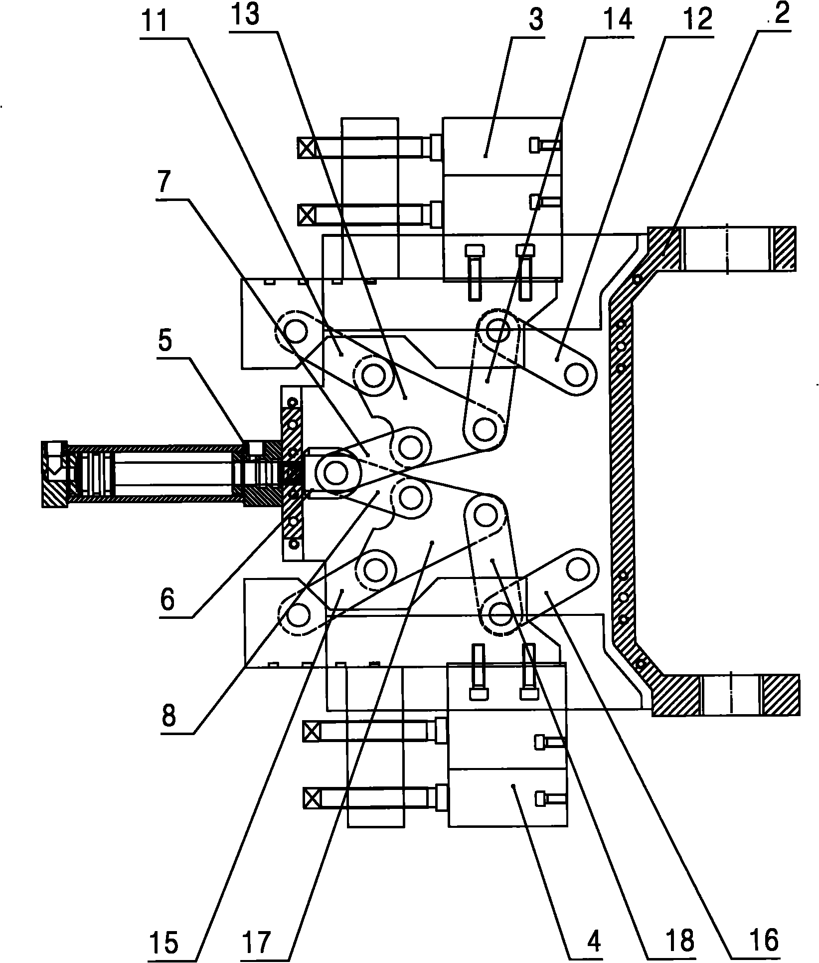
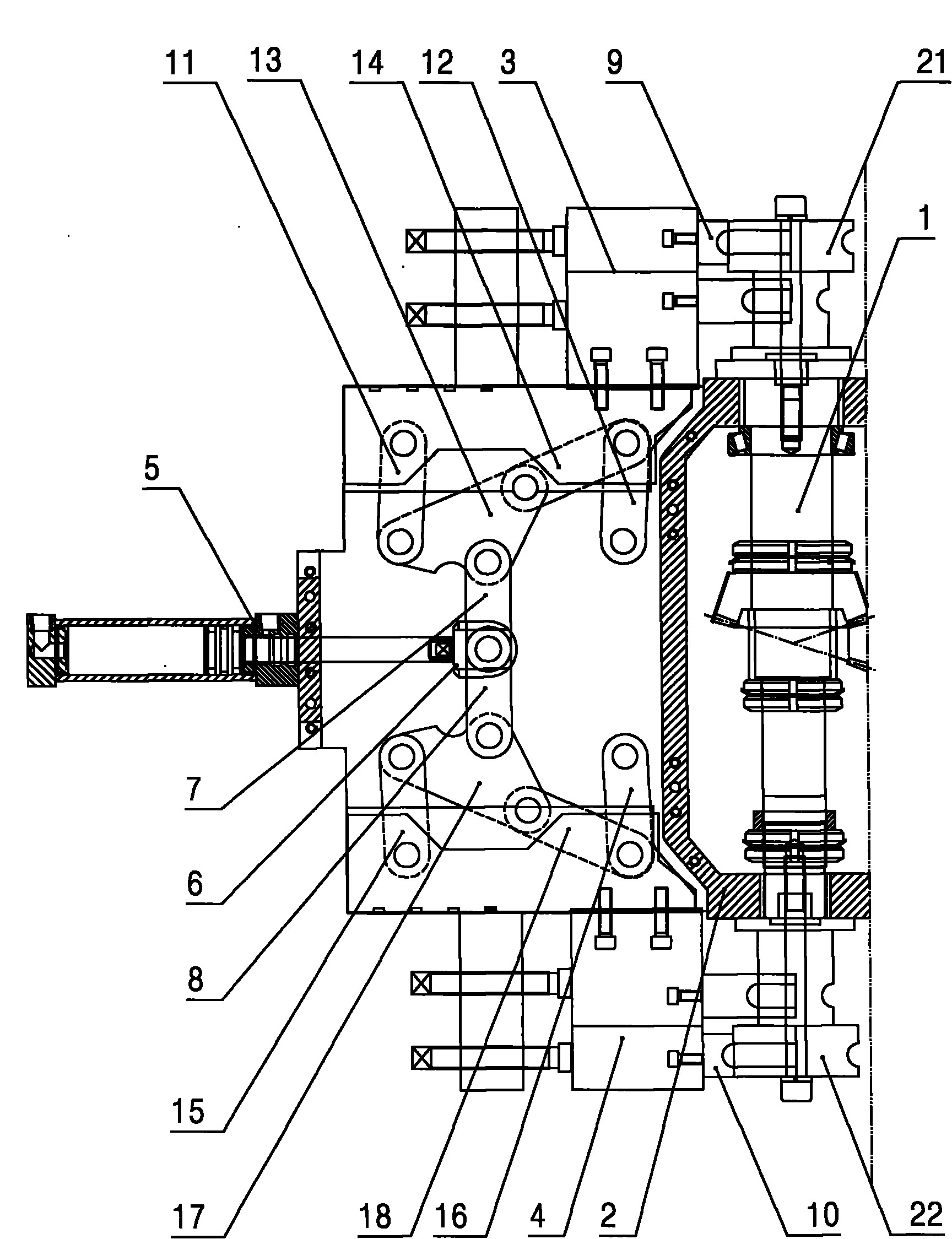
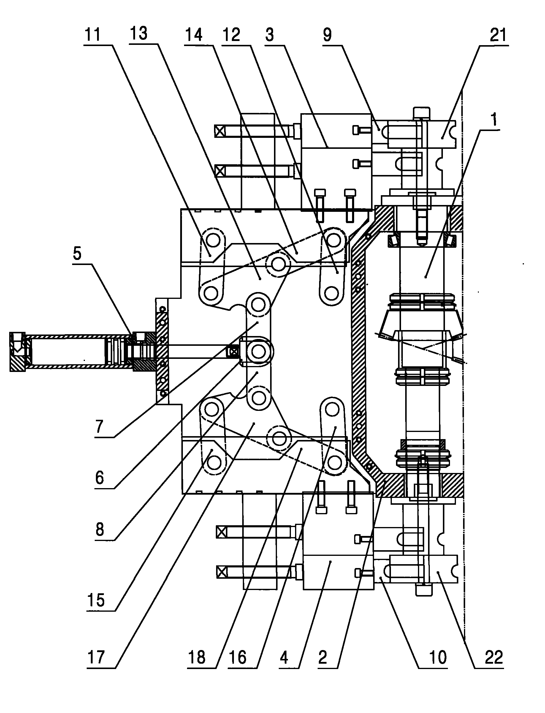
[0011] Such as figure 1 , figure 2 As shown, the driving device of the upper and lower clamping molds in the left and right integrated pipe bending machine of the present invention includes: a main shaft 1 that is movably arranged on the machine head, a pipe bending arm 2 is movably arranged on the main shaft 1, and two ends of the main shaft 1 The upper and lower wheel molds 21 and 22 are respectively provided at the ends, and the middle part of the main shaft 1 is provided with a bending arm 2, and the bending arm 2 is provided with upper and lower clamping molds corresponding to the upper and lower clamping molds 9 and 10 respectively. Seats 3 and 4, the elbow arm 2 is provided with a clamping oil cylinder 5 and upper and lower connecting rod groups corresponding to the upper and lower clamping mold seats 3 and 4 respectively, the piston ...


PUM


Abstract

The invention discloses a driving device of an upper clamp die and an lower clamp die of a left-right integrated pipe bending machine, which has the advantages of simple structure and low cost. The driving device comprises a machine head and a pipe bending arm movably arranged on the machine head, the pipe bending arm is provided with an upper clamp die seat, a lower clamp die seat, a clamp cylinder, an upper connecting rod group and a lower connecting rod group, wherein the upper clamp die seat and the lower clamp die seat respectively correspond to an upper clamp die and a lower clamp die, the upper connecting rod group and the lower connecting rod group respectively correspond to the upper clamp die seat and the lower clamp die seat, the end of the piston rod of the clamp cylinder is movably provided with a connecting rod, and the two ends of the connecting rod are respectively connected with the upper connecting rod group and the lower connecting rod group. The structure of the invention is very simple, the clamp cylinder is respectively connected with the upper connecting rod group and the lower connecting rod group through the connecting rod, thereby realizing the opening and closing motion of the upper clamp die and the lower clamp die and greatly reducing the manufacturing cost.

Description

technical field [0001] The invention relates to a left and right integrated pipe bending machine, in particular to a driving device for an upper and a lower clamping die in the left and right integrated pipe bending machine. Background technique [0002] At present, the left and right integrated pipe bending machines have a machine head that can rotate 180 degrees, and upper and lower wheel molds are respectively installed on the upper and lower ends of the main shaft. The upper and lower clamping molds matched with the mold and the driving device of the upper and lower clamping molds. When in use, the upper wheel mold, upper clamping mold and the driving device of the upper clamping mold can be operated, the pipe can be bent to the left, and the driving device of the lower wheel mold, lower clamping mold and lower clamping mold can be operated by rotating the machine head. Bend the pipe to the right. This kind of pipe bending machine can process some very complicated pipe...

Claims


Application Information

Patent Timeline
Patent Type & Authority Applications(China)
IPC IPC(8): B21D7/00B21D7/16
Inventor 赵叶静王艳秋
Owner ZHANGJIAGANG MINGHUA MACHINERY MFG
Learn More