
Indoor/outdoor detection

A circuit, strength technology, applied in the field of light-based control

Inactive Publication Date: 2010-07-14
NXP BV
View PDF0 Cites 37 Cited by
  • Summary
  • Abstract
  • Description
  • Claims
  • Application Information

AI Technical Summary

Problems solved by technology

Providing sufficient power to facilitate increased functionality in portable electronic devices while maintaining desired battery life has presented additional challenges

Method used


Image

  • Indoor/outdoor detection
  • Indoor/outdoor detection
  • Indoor/outdoor detection

Examples


Embodiment Construction

[0016] While the invention is susceptible to various modifications and alternative forms, specific details thereof have been shown by way of example in the drawings and will be described in detail. It should be understood, however, that the intention is not to limit the invention to the particular embodiments described. On the contrary, it is intended to cover all modifications, equivalents and alternatives falling within the scope of the invention including the scope defined by the appended claims.

[0017] The present invention is applicable to a variety of electronic circuits, devices and schemes including, for example, portable electronic devices that benefit from location-based control. While the present invention is not necessarily limited to this application, various aspects of the invention are best understood by discussing examples in this context.

[0018] According to example embodiments of the invention, sensors and processing circuitry facilitate detection of art...


PUM


Abstract

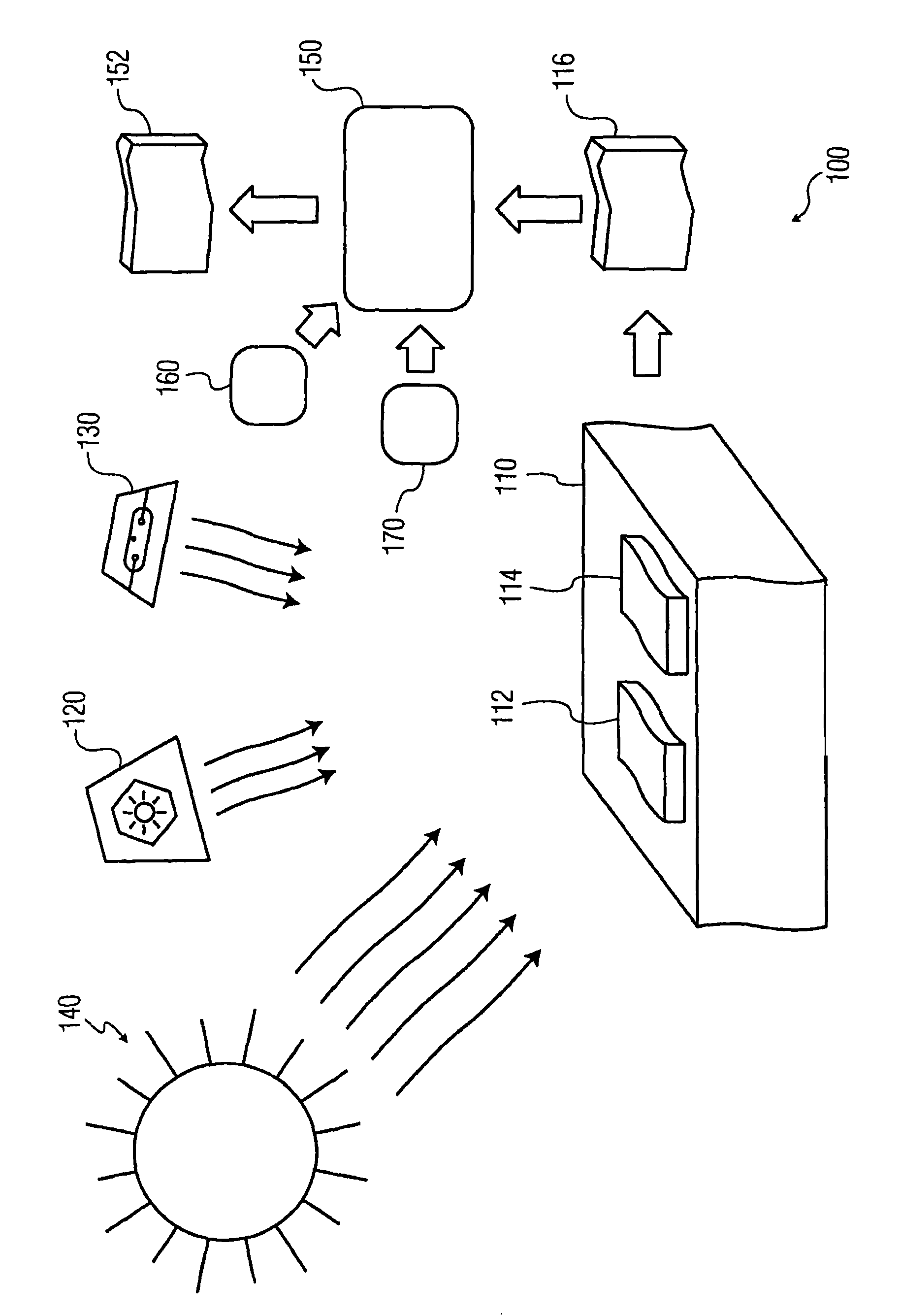
A light sensor is used to detect ambient light conditions. According to an example embodiment, a light sensor (112) detects color temperature and, in some instances, intensity characteristics of ambient light (120, 130, 140) in an environment and uses these detected characteristics (116) to determine the location of the sensor relative to natural and artificial light sources. This location determination is used to selectively operate circuits in a device such as a hand-held telephone, computer device or personal data assistant (PDA).

Description

technical field [0001] This patent document relates to portable devices, and more particularly to light-based control of electronic devices. Background technique [0002] In recent years, portable electronic devices have become increasingly popular. Due to rising popularity, there are demands on the features of these devices. For example, handheld devices such as PDAs, mobile phones, GPS devices or MP3 players have become equipped with an ever increasing number of features. Additionally, many portable devices are capable of using two or more communication schemes (e.g., involving wireless Internet (Wi-Fi) connections, Bluetooth connection, wireless phone connection, etc.) to communicate. [0003] Since all of these features require power to operate, the power requirements of these devices have increased with increased functionality. Correspondingly, as the power demands of these devices increase, the battery life of these devices tends to shorten. Battery life is an im...

Claims


Application Information

Patent Timeline
IPC IPC(8): G01J1/42G01J5/60G01J1/16H04M1/73
CPCH04M2250/12G06F1/1684G01J5/602H04W52/0277G01J1/4204G06F1/1613G01J1/4228Y02D30/70
Inventor 罗布·范达伦塞尔焦·马斯菲尔雷·欧卡拉
Owner NXP BV
Learn More