
Coating zone with inclined guide rails

A coating and guide rail technology, which is applied in the direction of spraying devices and spray booths, can solve the problems of not being too wide in the painting room and difficult to obtain guide rails

Active Publication Date: 2013-06-19
DUERR SYST GMBH
View PDF11 Cites 0 Cited by
  • Summary
  • Abstract
  • Description
  • Claims
  • Application Information

AI Technical Summary

Problems solved by technology

The main disadvantage of the known painting area is that the paint booth cannot be too wide in view of the construction and investment costs including the walk-in control area
On the one hand, the available space for the control area is undesirably too small
On the other hand, for a given overall width and enlargement of the control area, the passage for the air flow to flow down the ceiling in the booth is undesirably restricted
[0007] Another problem is the necessary support for the overhead arrangement rails, which are naturally more difficult to obtain than rails on the paint booth floor
So far, attempts have been made to achieve sufficient stability for the guide rails mounted above the conveyors on the chamber walls only with suboptimal constructions for corresponding stabilizing side walls, in particular without their own transverse rails at the height of these rails. rod

Method used


Image

  • Coating zone with inclined guide rails
  • Coating zone with inclined guide rails
  • Coating zone with inclined guide rails

Examples


Embodiment Construction

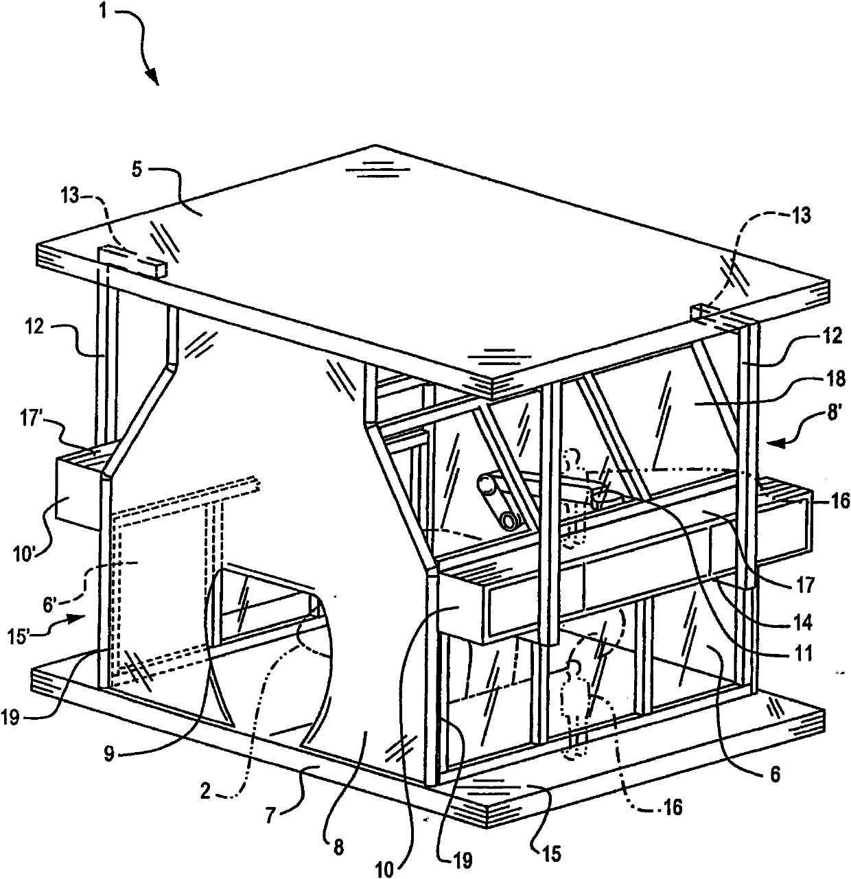
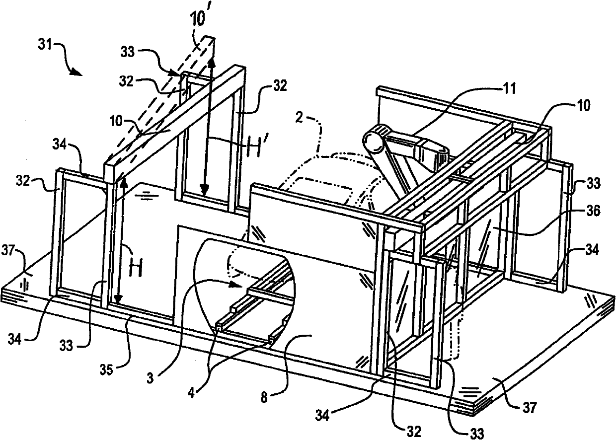
[0036] figure 1 The paint booth 1 for a vehicle body 2 shown in can form part of a paint booth. However, the painting area described here and below can also be arranged inside a wider painting booth. Can be used on conventional floor conveyors 3 (cf. image 3 , figure 1 Not shown in) the upper edge, for example, consists of guide rail 4 ( image 3 ) The conveying path defined by ) conveys the vehicle body through the coating booth 1 . The coating booth is delimited at the top by a horizontal top plate 5, on both sides by side walls 6 or 6' arranged parallel to the conveying path, at the bottom by a horizontal floor 7 and at the inlet and / or outlet end by a wall arranged perpendicular to the conveying path. The partition walls 8 and 8' are bounded. Furthermore, similar or different coating booths can be arranged one behind the other along the conveying path, for example in the same coating booth outside the partition walls 8 and / or 8'. In a conventional manner known per s...


PUM


Abstract

In a painting booth (1) for the series coating of application objects, such as vehicle bodies (2) or the add-on parts thereof, painting and / or handling robots (11) are moveable on guide rails (10) arranged above the conveyor (3) of the objects (2) and in particular arranged approximately level with their upper side or thereabove. According to a first aspect of the invention, the guide rail (10) and the basic body (51) of the robot (11), which basic body is guided by the guide rail, are arranged in such a manner that the first axis (A1) of the robot is inclined in relation to the vertical plane which is parallel to the conveying direction. According to a second aspect of the invention, the guide rail (10) is arranged at an inclination or tiltably with respect to a vertical plane which is parallel to the conveying direction.

Description

technical field [0001] The invention relates to a coating plant region and a coating plant having said region. It relates in particular to painting (painting) booths or other areas of installations for the continuous coating of coating objects, such as in particular car bodies, or accessories for this using robots, including painting or other coating robots, such as Other manipulators for additional devices and / or handling robots for opening tools such as doors or hoods. Background technique [0002] In conventional paint booths (paint booths) for painting car bodies using robots, guide rails therein are generally installed transversely on the floor of the paint booth. However, it may be more convenient to arrange the guide rails of the robot above the conveyor or even the vehicle body for various reasons, for example, because they interfere with viewing through the side walls of the paint booth and reduce the accessibility of the vehicle body or other coating objects , an...

Claims


Application Information

Patent Timeline
Patent Type & Authority Patents(China)
IPC IPC(8): B05B13/04
CPCB05B13/0431B05B15/1222B05B13/0452B05B15/1214B05B16/60B05B16/40
Inventor F·赫勒J·哈斯M·鲍曼M·弗赖H·韦特斯J·格里格莱特
Owner DUERR SYST GMBH
Learn More