
Automatic burnishing and polishing machine for stone sidelines

A grinding and polishing machine and stone technology, applied in grinding/polishing equipment, machine tools suitable for grinding the edge of workpieces, grinding machines, etc., can solve the problems of high price, small production specifications, high cost, etc., to improve productivity and quality, The effect of reducing requirements and improving efficiency

Inactive Publication Date: 2010-07-14
HUAZHONG UNIV OF SCI & TECH
View PDF0 Cites 15 Cited by
  • Summary
  • Abstract
  • Description
  • Claims
  • Application Information

AI Technical Summary

Problems solved by technology

However, there are the following disadvantages: only a single process can be completed, and different polishing wheels need to be designed and manufactured for different stone edge lines, resulting in low efficiency, high cost, and poor product quality; small and long lines are easily broken by the grinding wheel during polishing; grinding and polishing subject to many conditions
At present, there are similar production equipment in Europe and the United States in foreign countries, most of which are single-headed. Although there are multiple heads, the production specifications are small and the price is high. If this equipment is imported, the investment cost is very high.
At present, there is no domestic equipment for multi-process automatic processing of stone edges, and there are no reports of related patented products.

Method used


Image

  • Automatic burnishing and polishing machine for stone sidelines
  • Automatic burnishing and polishing machine for stone sidelines
  • Automatic burnishing and polishing machine for stone sidelines

Examples


Embodiment Construction

[0032] The present invention will be described in detail below with reference to the accompanying drawings.

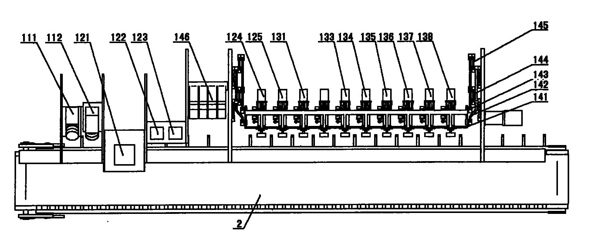
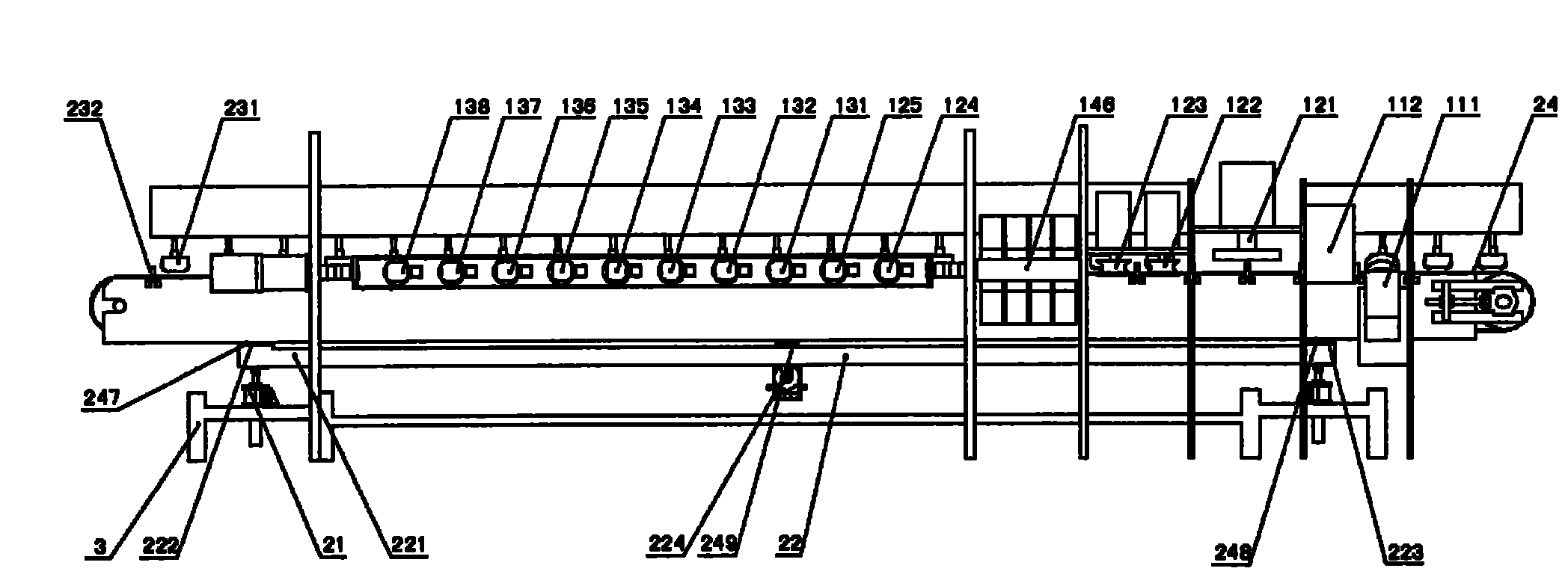
[0033] The stone edge automatic grinding and polishing machine adopts an assembly line structure, figure 1 It is the top view of the stone edge automatic grinding and polishing machine of the present invention, figure 2 It is the rear view of the stone edge automatic grinding and polishing machine of the present invention, Figure 7 It is a three-dimensional reference schematic diagram of the stone edge automatic grinding and polishing machine of the present invention.

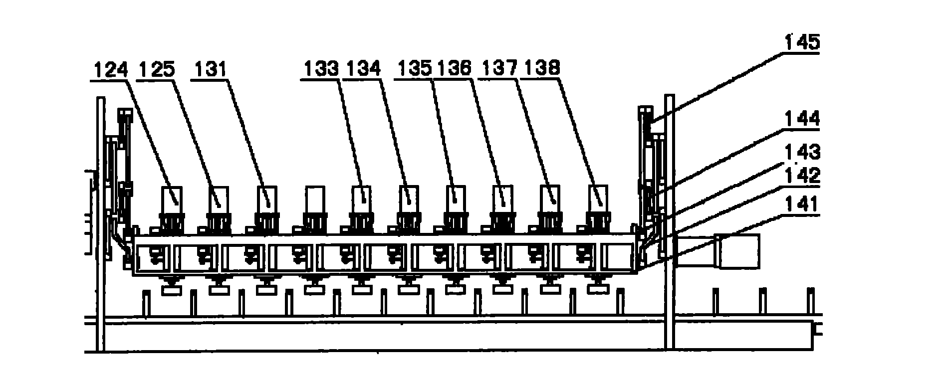
[0034] This equipment can be divided into three parts: processing head group, processing parts conveying line 2, frame 3. Four interlocking worm gear screw lifts 21 are installed on the stone material sideline automatic grinding and polishing machine frame 3, as a vertical positioning device, to realize the vertical positioning of the conveying platform. The support of worm wheel screw lifter 21 is...


PUM


Abstract

The invention discloses an automatic burnishing and polishing machine for stone sidelines, which relates to the technical field of machining stones, in particular to stone sideline machining equipment. The automatic burnishing and polishing machine has the purposes of automatically chamfering, burnishing and polishing the sides of the stone sidelines, and can improve the machining production efficiency and quality. The automatic burnishing and polishing machine for the stone sidelines has a streamline structure; a side chamfering machining head part, a thickening machining head part, a shaping milling machining head part and a swinging mechanism are arranged on a stander along the conveying direction of workpieces; a fine grinding machining head part and a polishing machining head part are arranged on the swinging mechanism; a conveying belt mechanism is arranged on a horizontal positioning device through a lead rail along the vertical direction of conveying the workpieces; the horizontal positioning device is arranged at the upper end of a vertical positioning device; the vertical positioning device is arranged on the stander; a pressing wheel component of a side positioning device is arranged on the upper stander of the conveying belt mechanism; a guide wheel component of the side positioning device is arranged on the conveying belt mechanism in the conveying direction of the workpieces on the upper edge of a panel on one side of the machining head group.

Description

technical field [0001] The invention relates to the technical field of stone processing, in particular to processing equipment for stone edges. Background technique [0002] Due to the high added value of special-shaped stone products with stone borders, whether it is modern architecture, interior decoration or stone furniture manufacturing, the demand for stone border products is increasing day by day. If stone edge processing is done manually or by single-process machining, the labor load is large, the production efficiency is low, the polishing cost is high, and it is difficult to meet the quality requirements. Therefore, it is very necessary to develop mechanical equipment specially for stone edge processing. [0003] At present, most of the processing of stone edges in domestic enterprises is still mainly manual. Even if the processing is done by mechanical equipment, it is simply refitted on lathes and other equipment. These processing technologies have low processing...

Claims


Application Information

Patent Timeline
IPC IPC(8): B24B9/06
Inventor 易传云郑利俊陈思扬江官庆熊烽
Owner HUAZHONG UNIV OF SCI & TECH
Learn More