Piezoelectric valve

A piezoelectric valve, pre-compression technology, applied in valve detail, valve device, valve operation/release device, etc., can solve problems such as closing force reduction, flow power limitation, etc.

Active Publication Date: 2011-11-09
HOERBIGER FLOW CONTROL GMBH
View PDF4 Cites 0 Cited by
  • Summary
  • Abstract
  • Description
  • Claims
  • Application Information

AI Technical Summary

Problems solved by technology

However, the force-travel-characteristic curve of the bending transducer places certain limitations on the application of piezoelectric valves, since the closing force may decrease with increasing deflection
Therefore, the flow power to be switched on by the piezo valve is typically limited, which is proportional to the product of the switched on flow rate and the differential pressure

Method used


Image

  • Piezoelectric valve
  • Piezoelectric valve

Examples


Embodiment Construction

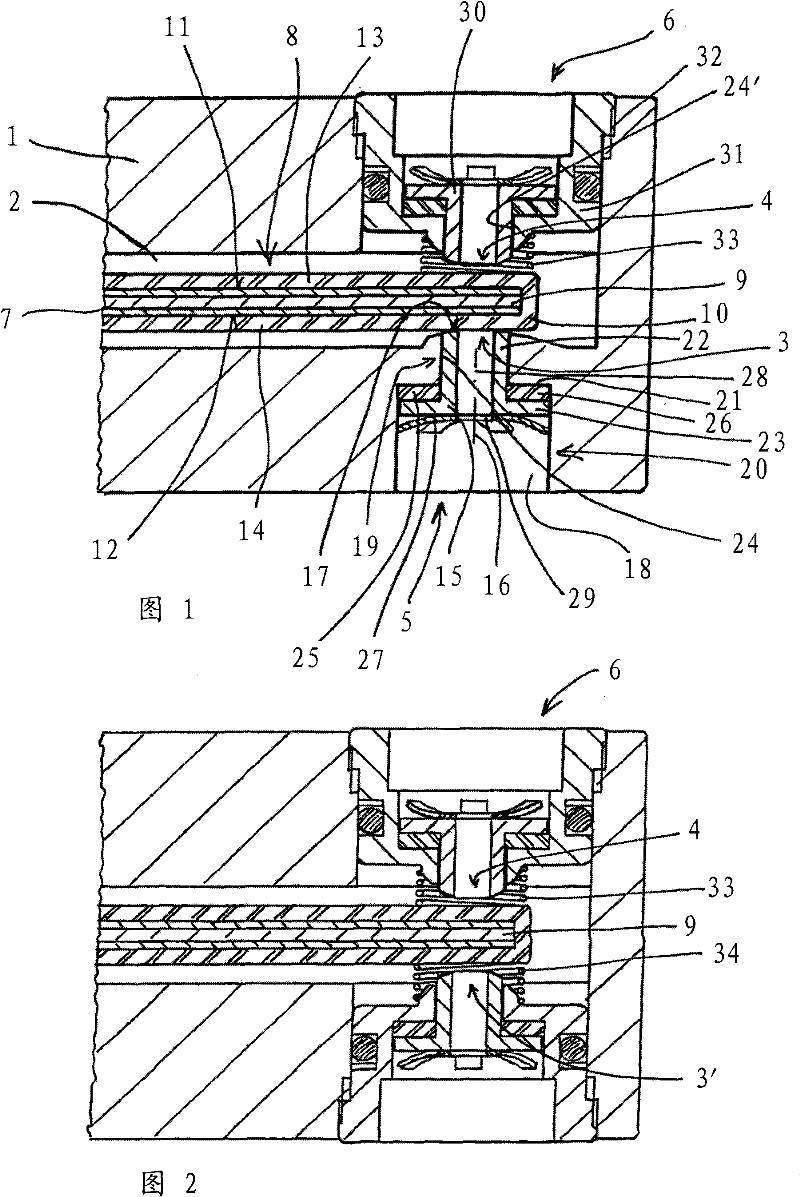
[0014] In terms of its basic structure, the figure 1 The piezo valve shown in the preferred embodiment corresponds to the piezo valve disclosed in EP 943812 A1 (US 6143744 B1). Therefore, a description of the piezoelectric valve in its entirety and the remaining design features is omitted, but full reference is made to the aforementioned publications in order to supplement the following explanation.

[0015] figure 1 The piezo valve shown in includes a housing 1 with an inner space 2 through which flow can flow. Two mutually opposite nozzles 3 and 4 open into the interior 2 , each communicating with an associated fluid medium connection 5 or 6 . Furthermore, the interior 2 of the housing 1 communicates in a known manner with an opening (not shown). In said inner cavity 2 of the housing 1 is mounted a piezoelectric bending element 7 deformable by energization such that one of the piezoelectric elements 7 changes its position relative to the housing when energized The region...


PUM


Abstract

The invention relates to a piezoelectric valve having a housing (1), comprising an inner chamber (2) through which a medium can flow, wherein at least one nozzle (3, 3'; 4) that communicates with an associated connection (5; 6) for the flow medium and having a sealing seat with a seat surface ends in said chamber. The inner chamber of the housing receives a piezoelectric flexible element (7) deformable by electric energization such that the nozzle (3, 3'; 4) can be closed by a section (9) of the flexible element, the section being moveable relative to the nozzle due to the deformation of the flexible element (7). The flexible element comprises a support (13; 14) in the region opposite the nozzle, the support being made of an elastic resilient material. The sealing seat is arranged on a nozzle insert (15; 30) on the front side, said insert being movably arranged substantially perpendicular to the seat surface (17) in a receptacle (24; 24') on the housing, wherein between the receptacleand the associated nozzle insert, a thermally expandable compensation member (25) acts.

Description

technical field [0001] The invention relates to a piezoelectric valve with a housing, which has a flow-through inner space, into which at least one nozzle of this type communicates, which nozzle is associated with a fluid medium interface. communicates and has a sealing seat with a seat surface, wherein an electrically deformable bending element is inserted into the inner cavity of the housing in such a way that the nozzle is closable by a section of the bending element, This section is displaceable relative to the nozzle due to the deformation of the bending element, and the bending element has a gasket made of elastic material at least in its region relative to the nozzle. Background technique [0002] Piezoelectric valves are known in numerous designs, for example DE 2511752 A1, DE 3400645 A1, DE 3527069 A1, EP 0404082 B1, EP 0538236 A1, DE 4320909 C1, DE 4410153 C1, WO 97 / 09555 A1, DE 19547649 A1, EP 10 B1, EP 105 and 0191 . Piezoelectric valves of this type are descri...

Claims


Application Information

Patent Timeline
Patent Type & Authority Patents(China)
IPC IPC(8): F16K31/00
CPCF16K31/006Y10T137/86622Y10T137/86847
Inventor 乔肯·谢布尔马库斯·格罗德尔
Owner HOERBIGER FLOW CONTROL GMBH
Why Eureka
Try Eureka