Dual-membrane micro-resistant ultrashort backflow preventer

A backflow preventer and diaphragm technology, applied in the direction of control valves, functional valve types, engine components, etc., can solve the problems of water supply safety hazards, easy loss, long structure, etc., to save installation space, ensure water supply safety, and low water head. effect of loss

Inactive Publication Date: 2010-06-23
刘永 +1
View PDF0 Cites 13 Cited by
  • Summary
  • Abstract
  • Description
  • Claims
  • Application Information

AI Technical Summary

Problems solved by technology

[0002] The current backflow preventer check valve adopts a "Y" type direct-flow structure, which is relatively long. Many renovation projects cannot be carried out as scheduled due to size problems. The drain valve adopts a "column"-shaped cavity structure or a "gourd"-shaped cavity structure. The control room adopts a single-diaphragm structure, and all control bypass pipes use external piping
On the one hand, the head loss of this structure is generally 7-9 meters. Because there are important structural design problems that have not been broken through, the head loss cannot be reduced. If this structure is used under the existing water supply conditions, the head loss will be large. Too many users cannot drink tap water, which is an important reason why this type of product cannot be promoted. On the other hand, when the diaphragm is damaged, it is difficult to determine whether the backflow water enters the upstream through the bypass pipe, which is not conducive to the safety of water supply. The through pipe is a weak point, easy to be lost, destroyed, or poisoned by bad people. It is a fatal problem that this type of product has not solved so far. Governments of various countries are well aware of the importance of this type of product, but because of the fatal weakness of this type of product However, the water safety of residents cannot be guaranteed, and the water supply of the entire town brings major safety hazards.

Method used


Image

  • Dual-membrane micro-resistant ultrashort backflow preventer
  • Dual-membrane micro-resistant ultrashort backflow preventer
  • Dual-membrane micro-resistant ultrashort backflow preventer

Examples


Embodiment Construction

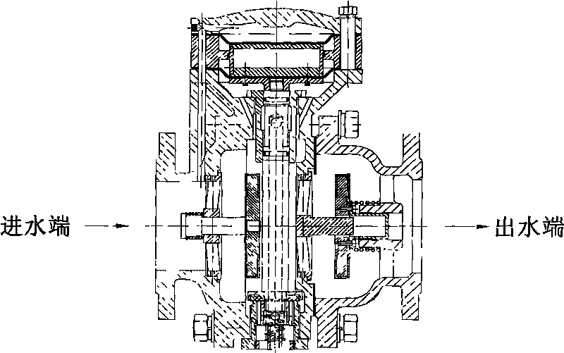
[0009] The structure of the double-diaphragm micro-resistance ultra-short backflow preventer of the present invention without an external catheter is described in conjunction with the accompanying drawings and embodiments.

[0010] The double-diaphragm micro-resistance ultra-short backflow preventer is a structure with a major breakthrough in the technical field.

[0011] Such as figure 1 as shown, figure 1 The middle arrow indicates the direction of medium flow. During normal water supply, the double-diaphragm micro-resistance ultra-short backflow preventer, the pressure water will open the check valve plate one (7) and the check valve plate two (20) to the right successively under the action of pressure water, and the water inlet The water enters the upper cavity of the control room through the through hole on the drain valve body (11) and through the through hole of the interlayer sleeve (15), so that no other external parts are needed to guide the water from the water in...


PUM


Abstract

The invention provides a dual-membrane micro-resistant ultrashort backflow preventer without a conduit. The backflow preventer comprises an inflow stop water-out valve and an effluent stop valve; valve bodies of the valve are fastened by a bolt and are communicated; a control chamber of the inflow stop water-out valve is provided with an interlayer sleeve; a guide pillar arranged in the control chamber is fixed in the middle of the control chamber by the interlayer sleeve; an upper membrane is arranged between a valve cover and the interlayer sleeve of the inflow stop water-out valve; an upper membrane is tiled on the top end surface of the guide pillar; a lower membrane is affixed on the bottom surface of the guide pillar and is fastened on the valve body of the inflow stop water-out valve with a bolt to form an upper cavity, double air isolating cavities and a lower cavity; a water-out valve rod of the inflow stop water-out valve is a hollow valve rod and communicated to outside air; an adjusting spring is arranged at the lower part of the water-out valve plate so as to adjust the minimum open pressure; and water from a water inlet of the inflow stop water-out valve enters through a through hole on the valve body and the interlayer sleeve into the upper cavity. The invention has the advantage that the backflow preventer with the structure is a combining device for flowing in single direction by strictly restricting pressure medium in a pipeline, has compact structure, saves installing space, can guide the backflow medium in the pipeline or medium in the critical backflow out of the pipe to form air isolation, does not need fittings, prevents malicious damage, ensures safe water supply, prevents pollution and is beneficial to observing and rapidly replacing membranes.

Description

technical field [0001] The invention relates to a valve structure, in particular to a double-diaphragm micro-resistance ultra-short backflow preventer. Background technique [0002] The current backflow preventer check valve adopts a "Y" type direct-flow structure, which is relatively long. Many renovation projects cannot be carried out as scheduled due to size problems. The drain valve adopts a "column"-shaped cavity structure or a "gourd"-shaped cavity structure. The control room adopts a single-diaphragm structure, and all control bypass pipes use external piping. On the one hand, the head loss of this structure is generally 7-9 meters. Because there are important structural design problems that have not been broken through, the head loss cannot be reduced. If this structure is used under the existing water supply conditions, the head loss will be large. Too many users cannot drink tap water, which is an important reason why this type of product cannot be promoted. On th...

Claims


Application Information

Patent Timeline
IPC IPC(8): F16K15/18F16K15/00
Inventor 刘永刘庆龚高石刘杰
Owner 刘永
Why Eureka
Try Eureka