


Quick Research
Generate reliable direction feasibility study reports for your R&D in just a few steps.

Technical Q&A
Discover and master advanced knowledge NOW. Basics, ideas, possibilities, all at once.

Find Solutions
As an expert in R&D theories, this can generate solutions to your technical problems instantly.

Evaluate Feasibility
Analyze your overall solution with one click, know your potential R&D risks in advance.

Monitor Landscape
Get weekly tech updates, stay abreast of the latest tech innovations and key insights.
Cylinder head for a self-igniting internal combustion engine
A cylinder head, internal combustion engine technology, applied in the direction of engine cooling, cylinder, cylinder head, etc., can solve problems such as damage to the cooling effect, and achieve the effect of prolonging service life, reducing flow loss, and increasing operating temperature
- Summary
- Abstract
- Description
- Claims
- Application Information
AI Technical Summary
Problems solved by technology
Method used
Image

Examples
Embodiment Construction
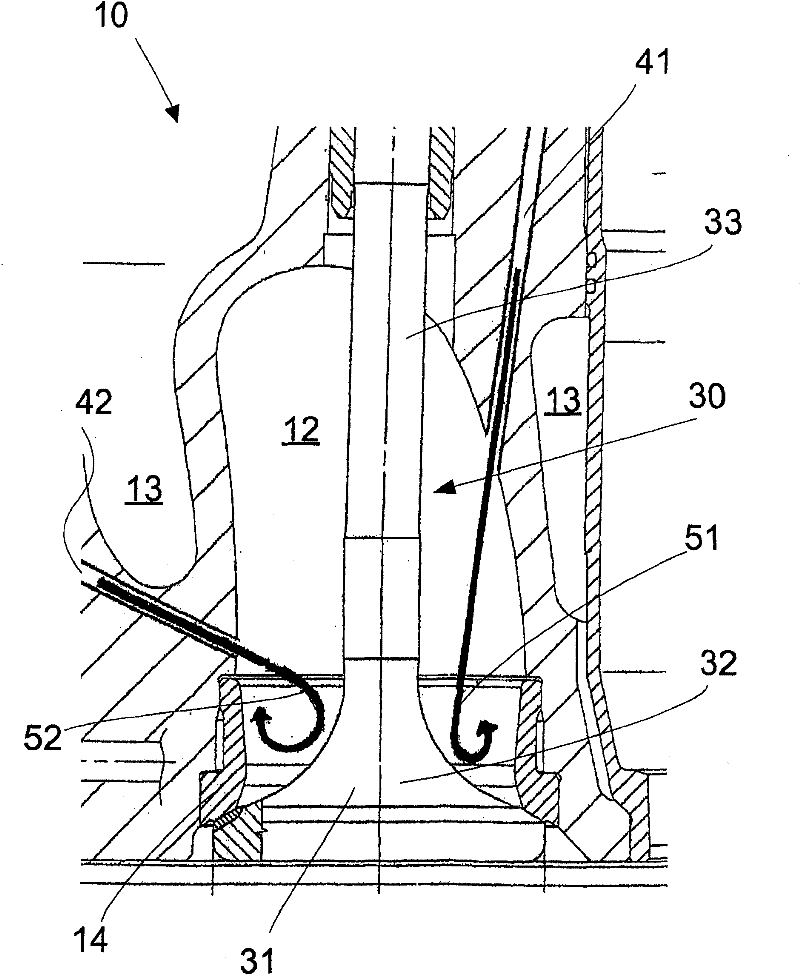
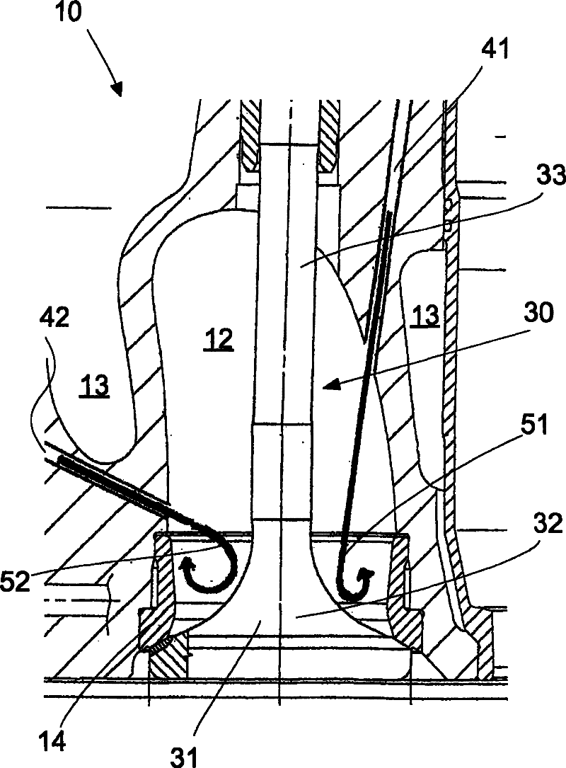
[0042] figure 1 An exemplary embodiment of a cylinder head 10 according to the invention is shown, which is shown in section in the region of the exhaust gas channel 12 . In the position shown, the exhaust valve 30 is seated in its seat region 31 . The exhaust channel is thus closed. In addition to the seat region 31 , the valve also includes a valve cone 32 and a valve foot 33 , which are mounted in the cylinder head outside the exhaust gas channel.
[0043] The cylinder head 10 itself is cooled by cooling water which circulates in a cooling jacket 13 which is only partially shown. The valve seat is formed by a separate valve seat ring 14 arranged in the cylinder head 10 , which is likewise water-cooled.
[0044] In the exemplary embodiment shown, the cooling air arrangement comprises two cooling air channels 41 and 42 which are introduced into the cylinder head 10 itself by means of bores in such a way that they run linearly through the cylinder head 10 . Cooling air duc...
PUM
 Abstract
Description
Claims
Application Information
 - R&D Engineer
- R&D Manager
- IP Professional
- Industry Leading Data Capabilities
- Powerful AI technology
- Patent DNA Extraction
Browse by: Latest US Patents, China's latest patents, Technical Efficacy Thesaurus, Application Domain, Technology Topic, Popular Technical Reports.
© 2024 PatSnap. All rights reserved.Legal|Privacy policy|Modern Slavery Act Transparency Statement|Sitemap|About US| Contact US: help@patsnap.com