Energy-dissipating and shock-absorbing supporting device
A technology of supporting devices and supporting components, which is applied in the direction of earthquake resistance and building components, can solve the problems of easy damage of the device, low energy consumption, unsuitability for super large and irregular buildings, etc., and achieves convenient installation, strong energy consumption, and extensive Shockproof effect
- Summary
- Abstract
- Description
- Claims
- Application Information
AI Technical Summary
Problems solved by technology
Method used
Image
Examples
Embodiment 1
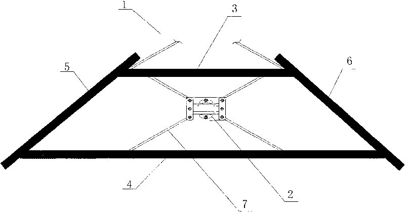
[0017] The frame 1 is an isosceles trapezoidal structure, the slope of the left leg 5 and the right leg 6 is 85°, and the two upper sides of the support member 7 are connected to the node where the upper beam 3 of the frame is connected to the left and right legs, Two of the lower sides are connected on the lower beam 4 of the frame. The support member 7 is braced with constrained buckling. The damper 2 is bolted to the support member 7 , and the support member 7 is welded to the frame 1 .
[0018] The center of the damper 2 coincides with the center of the frame 1 to ensure that the four support members 7 are on the same straight line as the corresponding diagonals of the damper 2 .
Embodiment 2
[0020] The frame 1 is an isosceles trapezoidal structure, the slope of the left outrigger 5 and the right outrigger 6 is 60°, and the four supporting members 7 are connected to the joints connecting the upper beam 3 and the lower beam 4 of the frame with the left and right outriggers . The support member 7 is braced with constrained buckling. The damper 2 is bolted to the support member 7 , and the support member 7 is riveted to the frame 1 .
[0021] The center of the damper 2 coincides with the center of the frame 1 to ensure that the upper two support members 7 are on the same line as the diagonals of the frame 1 .
Embodiment 3
[0023] The frame 1 is an isosceles trapezoidal structure, and the slope of the left outrigger 5 and the right outrigger 6 is 40°. The support members 7 are respectively connected to the upper beam 3 and the lower beam 4 of the frame. The support member 7 is braced with constrained buckling. The damper 2 is bolted to the support member 7 , and the support member 7 is bolted to the frame 1 .
PUM
| Property | Measurement | Unit |
|---|---|---|
| Slope | aaaaa | aaaaa |
Abstract
Description
Claims
Application Information
 - R&D
- Intellectual Property
- Life Sciences
- Materials
- Tech Scout
- Unparalleled Data Quality
- Higher Quality Content
- 60% Fewer Hallucinations
Browse by: Latest US Patents, China's latest patents, Technical Efficacy Thesaurus, Application Domain, Technology Topic, Popular Technical Reports.
© 2025 PatSnap. All rights reserved.Legal|Privacy policy|Modern Slavery Act Transparency Statement|Sitemap|About US| Contact US: help@patsnap.com


