
The method of rebuilding the diversion tunnel into a flood discharge tunnel by using the combined orifice energy dissipation technology

A technology of diversion tunnels and combined holes, which is applied in construction, water conservancy projects, sea area projects, etc., can solve the problems of insufficient energy dissipation, large discharge flow, increased cavitation cavitation, and high energy dissipation requirements, so as to avoid cavitation, Improvement of cavitation characteristics and improvement of energy dissipation rate

Inactive Publication Date: 2011-11-30
SICHUAN UNIV
View PDF0 Cites 0 Cited by
  • Summary
  • Abstract
  • Description
  • Claims
  • Application Information

AI Technical Summary

Problems solved by technology

Engineering practice shows that large-scale diversion tunnels often have the characteristics of large flow and high water head when rebuilding them, and the length of diversion tunnels that can be equipped with energy dissipators is limited. Therefore, the following problems exist in the use of hole-plug combined energy dissipators: 1. Due to the centrifugal force of the water flow, the risk of cavitation erosion on the wall of the plug-type energy dissipator increases; Insufficient energy dissipation and excessive discharge flow, or the discharge flow meets the design and the hole plug has cavitation and cavitation damage, and the unity of flood discharge and energy dissipation cannot be achieved)
The existence of the above problems will inevitably affect the safe operation of the converted flood tunnel

Method used


Image

  • The method of rebuilding the diversion tunnel into a flood discharge tunnel by using the combined orifice energy dissipation technology
  • The method of rebuilding the diversion tunnel into a flood discharge tunnel by using the combined orifice energy dissipation technology
  • The method of rebuilding the diversion tunnel into a flood discharge tunnel by using the combined orifice energy dissipation technology

Examples


Embodiment 1

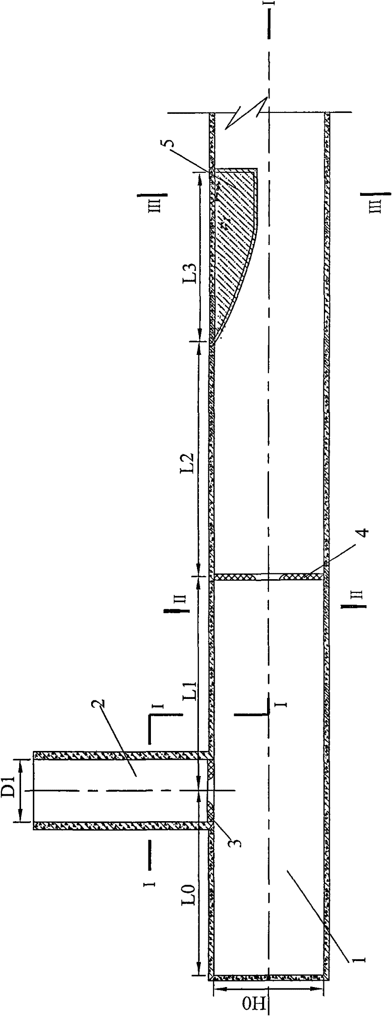
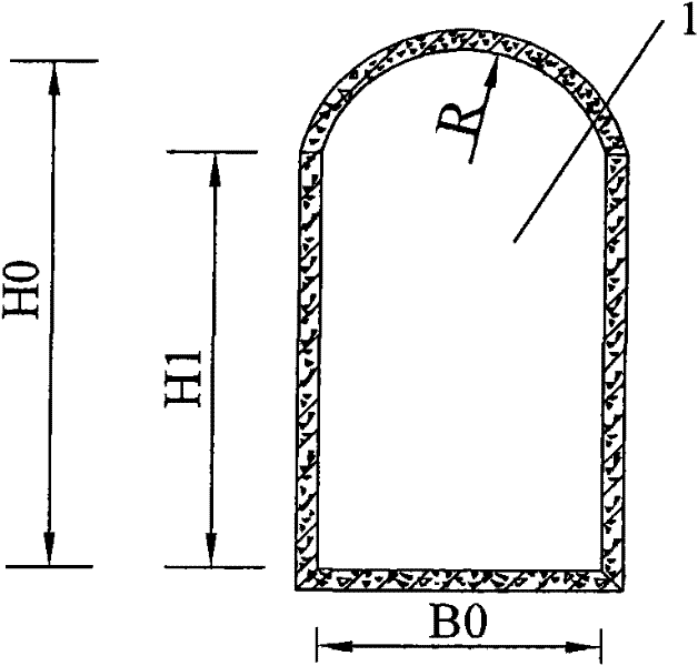
[0035] The water retaining structure of a water conservancy project adopts a concrete gravity dam, the maximum dam height is 204m, and the maximum flood discharge discharge of the project is about 13927m 3 / s (peak flow is 14800m 3 / s), the total flood discharge power is 11600MW, the maximum single-width discharge exceeds 124m / s, the installed capacity is 1600MW (4×400MW), and the discharge capacity of the flood discharge tunnel is 1300m 3 / s, has the characteristics of narrow river valley, high water head, large flow and high velocity. Reconstruction section 1 of diversion tunnel is in the shape of "city gate hole", width B0=16.0m, height H0=20.0m, height of straight wall section H1=16m, radius of vault R=3.5m. The operation of rebuilding the diversion tunnel by adopting the method of the present invention is as follows:

[0036] ① A vertical shaft 2 connected to the diversion tunnel is set at the closed end of the diversion tunnel reconstruction section 1. The shaft is cir...

Embodiment 2

[0042] The barrage of a hydropower station is a concrete face rockfill dam, the maximum dam height is 146m, the normal water storage level is 998.00m, and the adjusted storage capacity is 0.83×10⁸m 3 (The adjustment characteristic is seasonal adjustment, the storage capacity coefficient is 0.021), and the installed capacity is 240MW. 3 / s. The reconstruction section 1 of the diversion tunnel is circular, and its diameter D0 = 12m. The operation of rebuilding the diversion tunnel by adopting the method of the present invention is as follows:

[0043] ① A vertical shaft 2 connected to the diversion tunnel is set at the closed end of the diversion tunnel reconstruction section 1, the shaft is circular, its diameter D1=6m, and its centerline is perpendicular to the centerline of the diversion tunnel reconstruction section 1;

[0044] ②Set the vertical shaft orifice 3 at the connection between the vertical shaft and the reconstruction section of the diversion tunnel, and the vert...


PUM


Abstract

A method for rebuilding a diversion tunnel into a flood discharge tunnel by using combined orifice energy dissipation technology. The reconstruction operation is as follows: ① A vertical shaft connected with the diversion tunnel is set at the closed end of the diversion tunnel reconstruction section, and the center line of the vertical shaft is vertical at the centerline of the diversion tunnel reconstruction section; ②A first-level orifice plate is set at the connection between the shaft and the diversion tunnel reconstruction section, and the orifice plate is defined as the shaft orifice plate, and the shaft orifice plate is concentric with the centerline of the shaft; ③In At least one level of orifice plate is set in the diversion tunnel reconstruction section after the vertical shaft, and the orifice plate set in the diversion tunnel reconstruction section is defined as the diversion hole orifice plate, and the diversion hole orifice plate is on the same centerline as the diversion tunnel reconstruction section ; ④ At the outlet end of the reconstruction section of the diversion tunnel, set a gradual transition section from large to small.

Description

technical field [0001] The invention belongs to the field of water conservancy and hydropower engineering, and relates to a method for converting a diversion tunnel into a permanent flood discharge tunnel with a shaft. Background technique [0002] When the diversion tunnel is converted into a flood tunnel with a vertical shaft, the existing technology usually uses a combined energy dissipation device with plugs, that is, multi-level plugs are set for energy dissipation in the reconstruction section of the diversion tunnel. Engineering practice shows that large-scale diversion tunnels often have the characteristics of large flow and high water head when rebuilding them, and the length of diversion tunnels that can be equipped with energy dissipators is limited. Therefore, the following problems exist in the use of hole-plug combined energy dissipators: 1. Due to the centrifugal force of the water flow, the risk of cavitation erosion on the wall of the plug-type energy dissip...

Claims


Application Information

Patent Timeline
Patent Type & Authority Patents(China)
IPC IPC(8): E02B8/06
Inventor 张建民许唯临刘善均王韦邓军曲景学田忠张法星李进陈剑刚任成瑶李忠雷刚余飞
Owner SICHUAN UNIV
Learn More