
Shell and manufacture method thereof

一种制作方法、壳体的技术,应用在对表面涂布液体的装置、电气设备外壳/柜子/抽屉、离子注入镀覆等方向,能够解决产品周期延长、产品良率降低、易形成点墨等问题,达到亮丽金属质感、产品良率高、制程简单的效果

Inactive Publication Date: 2013-06-05
NANTONG BAISHENG PRECISION MACHINERY
View PDF5 Cites 0 Cited by
  • Summary
  • Abstract
  • Description
  • Claims
  • Application Information

AI Technical Summary

Problems solved by technology

One of the existing methods of making trademarks on vacuum coating products is to directly print patterns or letters on the topcoat layer on the product surface to obtain trademarks. In this method, due to the high surface tension of the topcoat layer, it is difficult for the ink to be evenly distributed on the surface that needs to be printed. position, it is easy to form ink spots, and the adhesion is poor, which is easy to cause the appearance defect of the trademark; on the other hand, because the printed pattern or letter is higher than the outer surface of the product, the pattern or letter is easy to be worn or even damaged during use. Flaking, which affects the appearance of the product
[0004] Another method is to hollow out the decorative layers on the surface of the product by laser engraving to form a score of the preset trademark, and then fill the score with ink to form a trademark. This method prolongs the product cycle due to the increase of the laser engraving process, and the laser The machine is easy to deviate, resulting in a decrease in the yield of the entire product, and the filled ink is located on the outermost layer, without a protective layer, and is easy to wear

Method used


Image

  • Shell and manufacture method thereof

Examples


Embodiment Construction

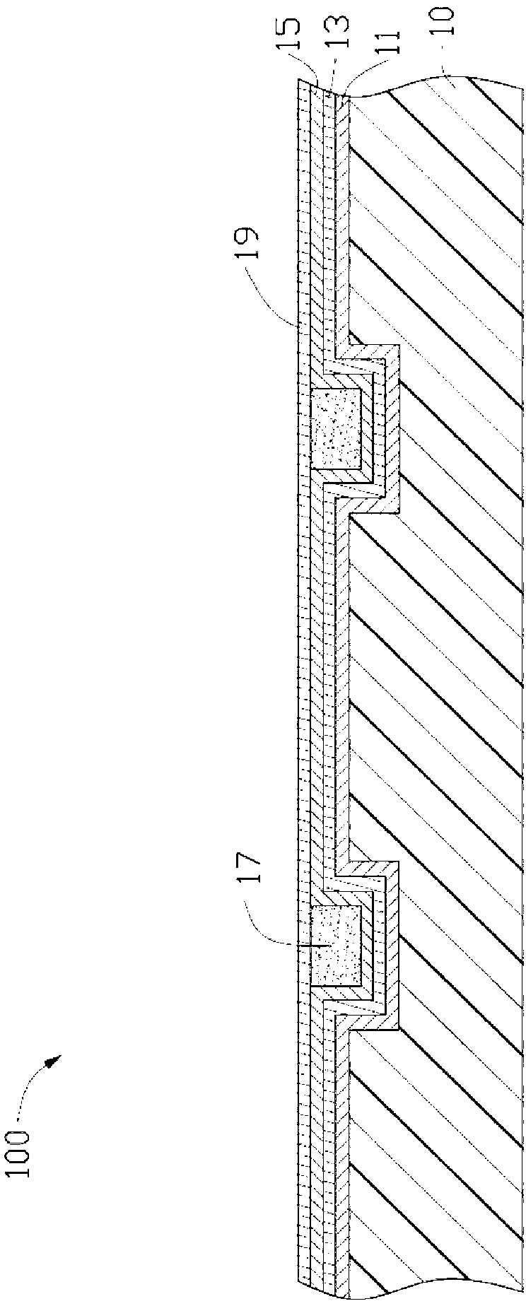
[0017] see figure 1 As shown, the housing 100 of the preferred embodiment of the present invention includes a substrate 10, a primer layer 11 formed on the substrate 10, a vacuum coating layer 13 formed on the primer layer 11, a vacuum coating layer formed on the vacuum coating layer The color paint layer 15 on 13, a pattern layer 17 formed on the color paint layer 15 and the transparent topcoat layer 19 covering the surface of the color paint layer 15 and the pattern layer 17.

[0018] The base 10 is a plastic base, and its surface is preset with a recessed area, and the recessed area has a preset trademark shape such as a pattern, a word or a character. The recessed area can be formed by arranging corresponding protrusions in the mold of the injection molding base 10 , or can be formed by chemical etching after the base 10 is molded.

[0019] The primer layer 11 is directly formed on the surface of the substrate 10 having the recessed area, which can be a UV-curable paint o...


PUM


Abstract

A device housing and a method of fabricating the device housing are provided. The device housing includes a base housing, a bottom coating, a vacuum evaporation coating, an intermediate coating, a fill coating and a top coating. The base housing is recessed to define a plurality of textured portions. The bottom coating is formed on the base housing and covers the textured portions. The vacuum evaporation coating is formed on the bottom coating. The intermediate coating is formed on the vacuum evaporation coating and has recessed sections corresponding to the textured portions. The fill coating is formed on the intermediate coating and fills the recessed sections. The top coating covers the intermediate coating and the fill coating.

Description

technical field [0001] The invention relates to a casing and a manufacturing method thereof. Background technique [0002] At present, vacuum coating the surface of the plastic shell of portable electronic devices such as mobile phones, digital cameras, personal digital assistants, and notebook computers to make their appearance have a metallic texture has become a common means to increase the added value of such products. [0003] After the vacuum coating is carried out on the surface of the plastic shell, one-color paint and one-side paint layer are usually applied on the surface of the vacuum coating layer. One of the existing methods of making trademarks on vacuum coating products is to directly print patterns or letters on the topcoat layer on the product surface to obtain trademarks. In this method, due to the high surface tension of the topcoat layer, it is difficult for the ink to be evenly distributed on the surface that needs to be printed. position, it is easy to...

Claims


Application Information

Patent Timeline
Patent Type & Authority Patents(China)
IPC IPC(8): H05K5/00C23C14/24B44C1/00
CPCB05D5/068H05K5/0243B05D7/02B05D7/57Y10T428/24521
Inventor 李洪波黄刚
Owner NANTONG BAISHENG PRECISION MACHINERY
Learn More