Interphase electromagnetic decoupling cylindrical permanent magnet linear synchronous motor

A permanent magnet synchronous linear and cylindrical technology, used in electrical components, electromechanical devices, electric components, etc., can solve the problem of large iron loss of the stator, and achieve the effect of improving efficiency, shortening magnetic circuit, and reducing eddy current loss.

Inactive Publication Date: 2012-06-27
HARBIN INST OF TECH
View PDF0 Cites 0 Cited by
  • Summary
  • Abstract
  • Description
  • Claims
  • Application Information

AI Technical Summary

Problems solved by technology

[0003] In order to solve the problem that the magnetic coupling between the phases affects the control accuracy of the current; and the shortcoming that the magnetic flux generated by the energization of each phase winding passes through a long magnetic circuit, the iron loss of the stator is relatively large, and a new method is proposed. A Cylindrical Permanent Magnet Synchronous Linear Motor with Interphase Electromagnetic Decoupling

Method used


Image

  • Interphase electromagnetic decoupling cylindrical permanent magnet linear synchronous motor
  • Interphase electromagnetic decoupling cylindrical permanent magnet linear synchronous motor
  • Interphase electromagnetic decoupling cylindrical permanent magnet linear synchronous motor

Examples


specific Embodiment approach 1

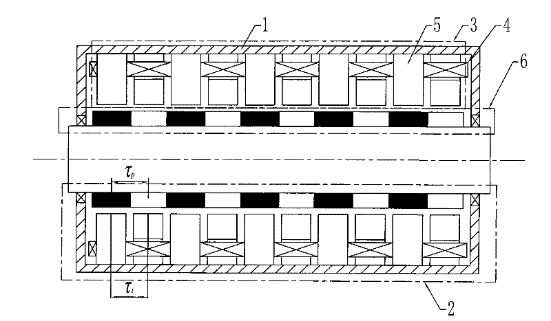
[0007] Specific implementation mode one: combine figure 1 , figure 2 , image 3 , Figure 4 with 12 To illustrate this embodiment, it is composed of a casing 1, a primary and a secondary 6; the secondary 6 is composed of a permanent magnet array and a shaft cylinder 61; the primary is composed of several phase units 2; each phase unit 2 is composed of several phase units Iron core 3 and phase winding 4; each phase unit iron core 3 is composed of 2k iron core units 5;

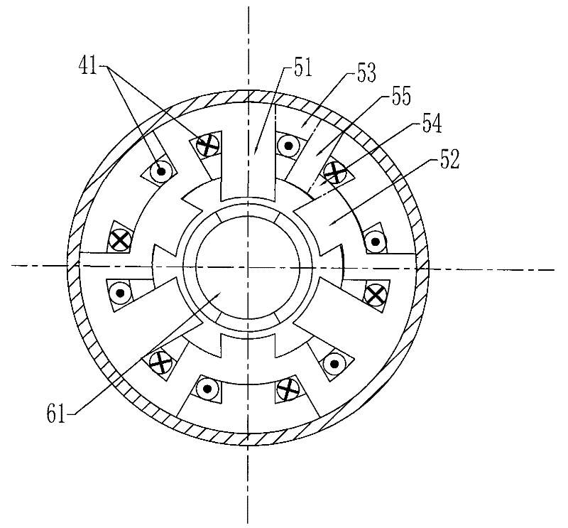
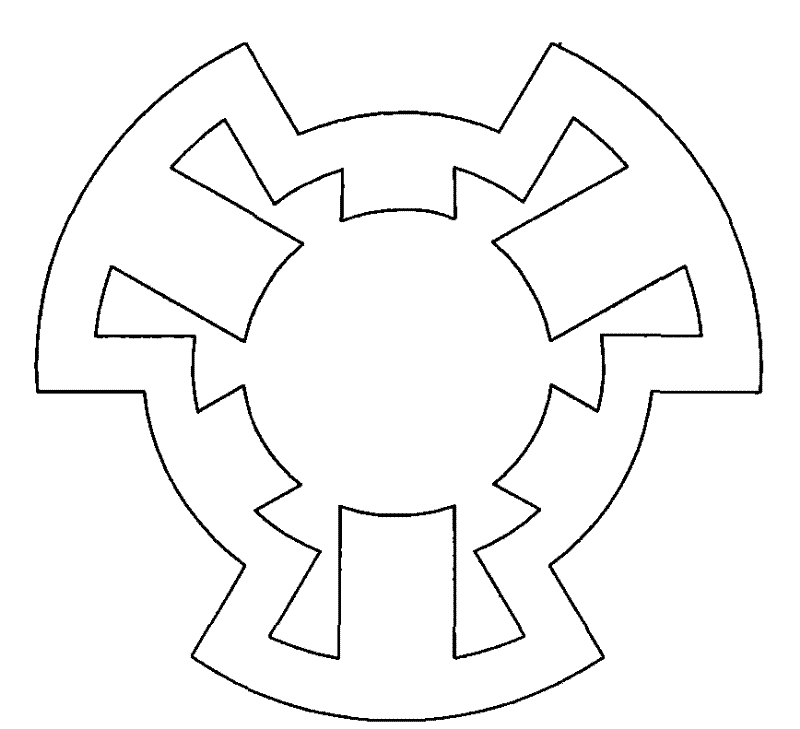
[0008] Each core unit 5 is made up of 2n teeth, 2n outer peripheral yoke segments 53, 2n inner peripheral yoke segments 54 and 2n radial yoke segments 55; 2n teeth are composed of n long teeth 51 and n short teeth teeth 52, n long teeth 51 and n short teeth 52 are arranged at equiangular intervals along the circumferential direction, and each long tooth 51 and each short tooth 52 are connected in turn with an outer peripheral yoke segment 53, a radial A yoke segment 55 and an inner peripheral yoke segment...

specific Embodiment approach 2

[0012] Embodiment 2: This embodiment differs from Embodiment 1 in that the shaft barrel 61 is cylindrical or cylindrical; the shaft barrel 61 is made of magnetically conductive or non-magnetically conductive material. Other compositions and connection methods are the same as those in Embodiment 1.

specific Embodiment approach 3

[0013] Specific implementation mode three: combination Figure 5 Describe this embodiment, the difference between this embodiment and the specific embodiment is that the permanent magnet array is composed of tile-shaped permanent magnets 62, and the magnetization direction of the tile-shaped permanent magnets 62 is radial magnetization, and the plurality of tiles Shaped permanent magnets 62 are adjacently arranged to form a permanent magnet circle along the circumferential direction, and 2q permanent magnet circles are arranged adjacent to each other along the axial direction, and the magnetization direction of every adjacent two tile-shaped permanent magnets 62 is opposite. Other compositions and connection methods are the same as those in Embodiment 1.


PUM


Abstract

The invention discloses an interphase electromagnetic decoupling cylindrical permanent magnet linear synchronous motor which relates to the field of motors and solves the problem that the control precision of current is influenced because magnetic coupling exists between phases and the defect that stator iron loss is larger because a magnetic circuit passed by magnetic flow generated by electrifying each group of windings is longer. Each primary phase unit of the permanent magnet linear synchronous motor comprises a phase unit iron core and a phase winding, wherein each phase unit iron core comprises 2k iron core units; the iron core units are characterized in that 2n outer peripheral magnet yoke sections, 2n radial magnet yoke sections and 2n inner peripheral magnet yoke sections are respectively connected between 2n long teeth and 2n short teeth in sequence; the peripheral directions of every two adjacent iron core units are staggered an angle of 360 degrees / 2n; each phase unit ironcore is arranged on radial magnetizing sections at the same position or the teeth are jointly wounded with a coil; 2n coils are sequentially connected in series or in parallel to form phase windings;and the winding direction of each coil is the same. The motor comprises im phase units when being an m-phase motor, and the center distance L between the iron cores of two adjacent phase units is shown as follows: L=[(j-1)+(1 / m)] tau p. The permanent magnet linear synchronous motor can be used as an electromotor or a generator.

Description

technical field [0001] The invention relates to the field of motors, in particular to a cylindrical permanent magnet synchronous linear motor. Background technique [0002] The structure of the existing cylindrical permanent magnet linear synchronous motor is as follows Figure 14 shown. When the armature core is made of silicon steel sheets, since the direction of the laminations is axial, the direction of the armature magnetic field generated by the permanent magnet and the winding is partly in the same direction as the laminations, forming a large eddy current in the core, resulting in a larger Large eddy current loss, and the iron core lamination process is complicated, and the processing cost is high; if a solid iron core is used, although the process is simple and the cost is low, the iron core will generate greater eddy current loss, which greatly reduces the efficiency of the motor. At the same time, due to the existence of magnetic coupling between phases, on the o...

Claims


Application Information

Patent Timeline
Patent Type & Authority Patents(China)
IPC IPC(8): H02K41/03
Inventor 寇宝泉贵献国
Owner HARBIN INST OF TECH
Why Eureka
Try Eureka