
Intelligent electronic leakage protector

A leakage protector, intelligent technology, applied in emergency protection circuit devices, emergency protection devices with automatic disconnection, instruments, etc., can solve the problems of simple functions of leakage protectors and the inability to effectively use the information transmission function of smart meters, and achieve The effect of reducing maintenance costs

Active Publication Date: 2012-11-21
浙江永信电气科技股份有限公司 +1
View PDF0 Cites 0 Cited by
  • Summary
  • Abstract
  • Description
  • Claims
  • Application Information

AI Technical Summary

Problems solved by technology

[0004] What the present invention aims to solve is that the existing leakage protectors have simple functions and cannot effectively use the information transmission function of the smart meter, so that the electricity department can keep abreast of the electricity consumption of terminal residents and the safety of electricity consumption, and actively make maintenance plans to ensure Issues of customer satisfaction and reduced maintenance costs

Method used


Image

  • Intelligent electronic leakage protector
  • Intelligent electronic leakage protector
  • Intelligent electronic leakage protector

Examples


Embodiment approach 1

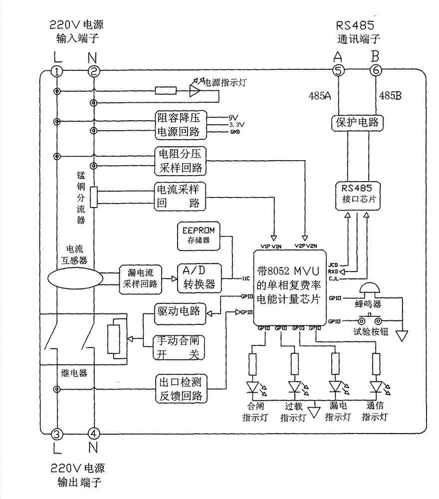
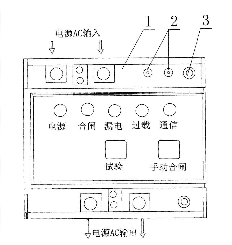
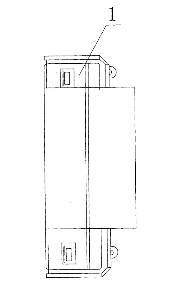
[0014] like figure 1 , figure 2 and image 3 As shown, the intelligent electronic leakage protector of the present invention includes a casing 1, a high-current relay and a current transformer arranged in the casing 1, and the current transformer is connected to the input end of the high-current relay. The housing 1 is provided with a single-phase multi-rate electric energy metering chip, and the single-phase multi-rate electric energy metering chip is connected with an interface chip for communication and a leakage current sampling device connected through an A / D converter for collecting leakage current. loop (unit), a current sampling loop (unit) for collecting current, a resistor divider sampling loop (unit) for collecting voltage, a drive circuit (unit) for driving a relay, and a current detection circuit for relay output The exit detection feedback loop (unit), the single-phase multi-rate electric energy metering chip processes and controls the signals from the interfa...

Embodiment approach 2

[0021] like Figure 4 As shown, the intelligent electronic leakage protector of the present invention includes a housing, a high-current relay and a current transformer located in the housing, the current transformer is connected to the high-current relay and has an input terminal, and a central processing unit is arranged in the housing. The central processing unit is connected with an electric energy metering chip for measuring electricity, an interface chip for communication, a leakage current sampling circuit (unit) for collecting leakage current, a driving circuit (unit) for driving a relay, and a relay output terminal The outlet detection feedback loop (unit) of current detection, the central processing unit is used to process and control the signals from the electric energy metering chip, the interface chip, the leakage current sampling loop, the drive circuit and the outlet detection feedback loop; the leakage current sampling loop and the current mutual inductance The...


PUM


Abstract

The invention discloses an intelligent electronic leakage protector, which comprises a shell, and a heavy-current relay and a current transformer arranged in the shell, wherein the current transformer is connected with an input end of the heavy-current relay; a single-phase multi-rate electric energy measurement chip is also arranged in the shell; and an interface chip, a leakage current samplingloop, a current sampling loop, a resistance voltage-dividing sampling loop, a driving circuit and an outlet detection feedback circuit are connected to the single-phase multi-rate electric energy measurement chip. The intelligent electronic leakage protector fully and effectively uses an information transmission function of an intelligent electric meter to make an electricity utilization department grasp electricity utilization conditions and safe electricity utilization conditions of terminal residents in real time, and work out a maintenance program initiatively so as to ensure that users are satisfied and the maintenance cost is reduced.

Description

technical field [0001] The invention relates to a device used in a power system, in particular to an intelligent electronic leakage protector. Background technique [0002] The existing leakage protector only has simple functions, such as basic leakage protection function, automatic closing function, etc., but this kind of protector cannot simultaneously realize leakage current detection, electric energy detection, current detection, voltage Detection, power detection, trip control, RS485 communication or carrier communication, sound and light alarm, manual test and other functions. Therefore, the existing leakage protector cannot effectively use the information transmission function of the smart meter, so that the electricity department can keep abreast of the electricity consumption and safety of the terminal residents, and actively make maintenance plans to ensure customer satisfaction and reduce maintenance costs. Contents of the invention [0003] The purpose of the ...

Claims


Application Information

Patent Timeline
Patent Type & Authority Patents(China)
IPC IPC(8): H02H3/32G01R31/02G01R11/57
Inventor 钱金华徐光年蒋海忠
Owner 浙江永信电气科技股份有限公司
Learn More