Distributed DC ground fault detector

A DC grounding and fault detection technology, which is applied in the direction of measuring devices, fault locations, and measuring electricity, can solve problems such as failure to detect, switching value or remote signal misoperation, and difficulty in troubleshooting

Active Publication Date: 2010-06-16
山东惠工电气股份有限公司
View PDF1 Cites 38 Cited by
  • Summary
  • Abstract
  • Description
  • Claims
  • Application Information

AI Technical Summary

Problems solved by technology

[0004] 1. Balanced bridge method: The basis of the balanced bridge method is the principle of Wheatstone bridge balance. The disadvantage of the balanced bridge method is that it can only detect the insulation status of the entire DC system. , the method cannot detect
Even if the alarm can be issued, it is impossible to determine which branch circuit has a DC ground fault, which brings difficulties to troubleshooting
[0005] 2. Unbalanced bridge method: The unbalanced bridge method is developed on the basis of the balanced bridge method. The purpose is to solve the problem that the balanced bridge method cannot detect the balanced ground fault of the DC system, but it is also impossible to determine which branch A DC ground fault has occurred
[0008] To sum up, the four detection methods have their own advantages and disadvantages, and none of them can ensure the location of the DC grounding of the branch 100%, and when the DC grounding occurs in other branches, it may cause the switching value or remote signal used by the microcomputer protection. wait for misoperation

Method used


Image

  • Distributed DC ground fault detector
  • Distributed DC ground fault detector
  • Distributed DC ground fault detector

Examples


Embodiment 1

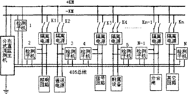
[0025] The device includes a DC power supply circuit, each branch of the DC power supply circuit is equipped with a grounding detection device, the grounding detection device includes an isolated power supply and a detection sub-machine, the positive and negative bus bars of the DC power supply are connected to each branch through the isolation power supply; one end of the detection sub-machine It is connected to the output of the isolated power supply, and the other end is connected and communicated with the DC detection host through the data transmission bus.

[0026] A detection sub-machine is arranged between the DC power supply bus and the data transmission bus. The data transmission bus adopts RS485 form. The detection sub-machine includes an unbalanced bridge, an isolated operational amplifier, an A / D converter, and a CPU. The input of the unbalanced bridge is connected to the isolated power supply, and the output is connected to the A / D converter and the CPU through th...

Embodiment 2

[0030] When there are many opening and closing circuits in the substation, and the user is unwilling or unable to use the isolated power supply to isolate the DC power supply of the opening and closing circuits, a hybrid DC grounding detection combining distributed and centralized methods can be used, and the others are the same as in Embodiment 1.

Embodiment 3

[0032] The isolated power supply 1 generates the isolated DC voltage of the busbar, and the isolated power supply 2 generates various working voltages required for the detection sub-machine, that is, the power supply DC power used for the detection sub-machine and the isolated DC power supply of the branch pass through two different isolated power supplies respectively. powered by. Others are with embodiment 1.


PUM


Abstract

The invention relates to a detector for electrical fault, in particular relating to a fault detector in transmission lines. A distributed DC ground fault detector in the invention comprises a DC power supply circuit each branch of which is provided with a ground detector, the ground detector is composed of an isolated power and a detecting sub-unit, and the positive and negative buses of the DC power are connected with each branch by the isolated power; and one end of the detecting sub-unit is connected with the isolated power, and the other end thereof is connected with a DC detecting host for communication by a data transmission bus. The distributed DC ground system of the invention has higher precision for judging fault than that of a centralized DC grounding system, and can be widely used in various power systems.

Description

technical field [0001] The invention relates to a detection device for electrical faults, in particular to a fault detection device in a transmission line. Background technique [0002] The DC system of power plants and substations is relatively complex, it needs to supply power, emergency lighting, control, signal, relay protection and automatic devices, AC uninterruptible power supply, etc., which play an extremely important role in the reliable operation of power plants and substations . One-point grounding occurs in the DC system. If the search is not timely, the second point grounding may occur. After a two-point ground fault occurs in the DC system, it may form a ground short circuit, causing relay protection, signal, and automatic devices to malfunction or refuse to operate, or cause DC fuses to blow, causing protection, automatic devices, and control circuits to lose power. It directly threatens the safety of primary equipment, so the power system has high requirem...

Claims


Application Information

Patent Timeline
Patent Type & Authority Applications(China)
IPC IPC(8): G01R31/08G01R31/02
Inventor 冯俊博李洪景
Owner 山东惠工电气股份有限公司
Why Eureka
Try Eureka