
Drive circuit and method of backlight unit

A technology of backlight unit and driving circuit, which is applied in the direction of electric lamp circuit layout, light source, electric light source, etc., can solve the problems of power consumption of voltage conversion circuit, and achieve the advantages of reducing power consumption, stable equivalent load, and more flexible dimming function. Effect

Active Publication Date: 2010-06-09
华映视讯(吴江)有限公司 +1
View PDF0 Cites 6 Cited by
  • Summary
  • Abstract
  • Description
  • Claims
  • Application Information

AI Technical Summary

Problems solved by technology

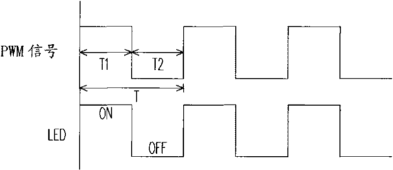
like Figure 4 As shown, when the PWM signal performs potential switching, the voltage conversion circuit will enter the discontinuous conduction mode (Discontinuous Conduction Mode, referred to as DCM mode), resulting in power consumption of the voltage conversion circuit

Method used


Image

  • Drive circuit and method of backlight unit
  • Drive circuit and method of backlight unit
  • Drive circuit and method of backlight unit

Examples


Embodiment Construction

[0041] Figure 5A It is an LED driving circuit diagram according to an embodiment of the present invention. The driving circuit 500 is used to drive the backlight unit 540 , which includes a voltage conversion circuit 510 , a driving unit 520 and a digital dimming unit 530 . The backlight unit 540 includes a plurality of LED strings (not shown), and each LED string includes at least one LED. The voltage conversion unit 510 is coupled to the backlight unit 540 and is mainly used to convert the level of the DC voltage, such as a DC-DC converter such as a boost circuit or a buck circuit. , the input voltage V IN The driving voltage required for the backlight unit 540 is converted. The driving unit 520 is coupled between the other end of the backlight unit 540 and the digital dimming unit 530 . Generally speaking, the driving unit 520 is mainly used to adjust the conduction current of the LED and perform dimming functions, such as dimming, which can be replaced by the driving ...


PUM


Abstract

The invention relates to drive circuit and method of a light-emitting diode backlight unit. The drive circuit comprises a voltage converting circuit, a drive unit and a digital dimming unit, wherein the drive unit can correspond to an enabled light-emitting diode string according to a digital signal output by the digital dimming unit and adjust the luminance of the backlight unit according to theenabling proportion of the light-emitting diode string.

Description

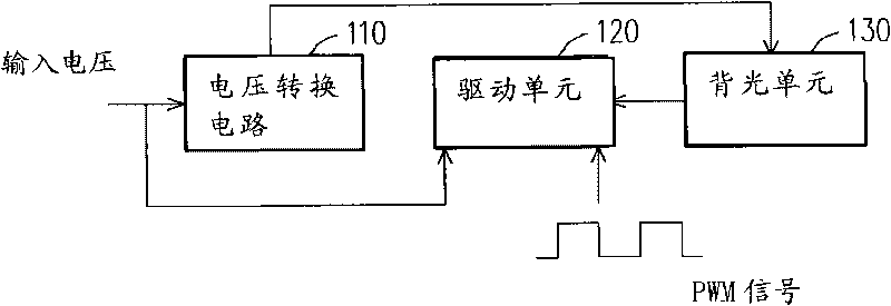
technical field [0001] The present invention relates to a driving circuit for a Light Emitting Diode (LED for short), and in particular relates to a driving circuit and a driving method for driving an LED with a digital signal. Background technique [0002] Such as figure 1 as shown, figure 1 It is a circuit diagram of an LED backlight driving circuit according to the known technology. For the backlight drive circuit part, it is mainly composed of a voltage conversion circuit 110 and a drive unit 120. The backlight unit 130 is composed of a plurality of light-emitting diode strings (referred to as LED strings) (not shown), and each LED string includes a plurality of LEDs. . The brightness of the backlight unit 130 can be adjusted through the magnitude of the current passing through the LED strings. figure 1 The resistor R shown in EXT That is, it is used to set the constant current value through the LED string, and the dimming control signal V CTRL It is used to contro...

Claims


Application Information

Patent Timeline
IPC IPC(8): H05B37/02
Inventor 陈鸿祥朱益男
Owner 华映视讯(吴江)有限公司
Learn More