
Light-emitting device, backlight module and LCD

A liquid crystal display and lighting device technology, applied to lighting devices, components of lighting devices, instruments, etc., can solve the problems of reducing the brightness of the backlight module, low luminous efficiency of the light emitting device 100, and reducing the luminous efficiency of the light emitting device 100, etc., to achieve improved Luminous efficiency, good light uniformity, and the effect of improving display quality

Active Publication Date: 2014-07-30
INNOLUX CORP
View PDF5 Cites 0 Cited by
  • Summary
  • Abstract
  • Description
  • Claims
  • Application Information

AI Technical Summary

Problems solved by technology

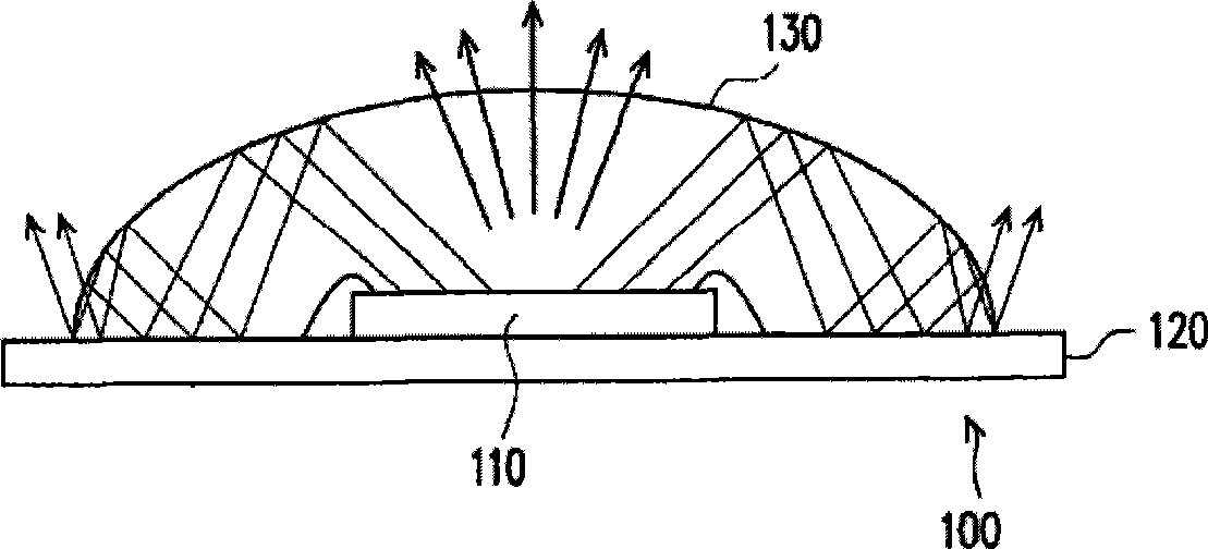
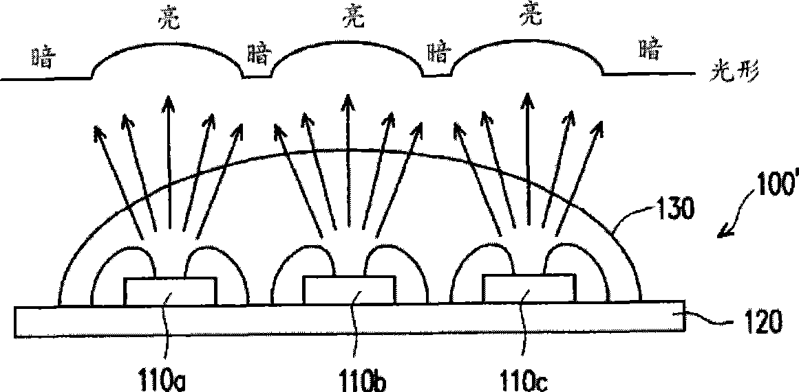
However, compared with the light-emitting devices packaged into single pieces, the light-emitting device 100 in which the light-emitting chip 110 is arranged on the substrate 120 is applied in the backlight module, and the luminous efficiency of the light-emitting device 100 is much lower than that of a single light-emitting device.
The reason is that when the light-emitting chip 110 emits light, only part of the light leaves the sealant 130 and is seen by the user, while the rest of the light will be totally reflected due to the difference in refractive index between the sealant 130 and air. phenomenon, so the luminous efficiency of the light-emitting device 100 is reduced, thereby reducing the brightness of the backlight module and affecting the display quality of the liquid crystal display.

Method used


Image

  • Light-emitting device, backlight module and LCD
  • Light-emitting device, backlight module and LCD
  • Light-emitting device, backlight module and LCD

Examples


no. 1 example

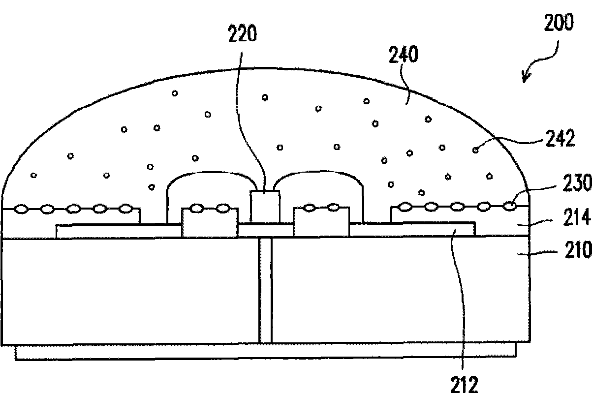
[0067] Figure 2A It is a schematic diagram of a light emitting device according to an embodiment of the present invention. Please refer to Figure 2A , the light emitting device 200 includes a substrate 210 , a light emitting chip 220 , a plurality of scattering particles 230 and an encapsulant 240 . The light-emitting chip 220 , the scattering particles 230 and the encapsulant 240 are all disposed on the substrate 210 , wherein the scattering particles 230 are distributed on the substrate 210 and located beside the light-emitting chip 220 . The encapsulant 240 covers the light-emitting chip 220 and at least part of the scattering particles 230 . When the light-emitting chip 220 emits light, the light totally reflected because the refractive index of the encapsulant 240 is greater than that of air will hit the scattering particles 230 and then be reflected by the scattering particles 230 to the outside of the encapsulant 240 . Therefore, the light emitting device 200 of th...


PUM


Abstract

The invention relates to a light-emitting device, a backlight module and an LCD. The backlight module comprises a framework and a light source, wherein the light source is arranged in the framework. The light source comprises a substrate and a plurality of light-emitting devices, wherein each light-emitting device contains at least one light-emitting chip, a plurality of scattering particles and a sealing wax; and the light-emitting chip, scattering particles and sealing wax are all arranged on the substrate, wherein the scattering particles are next to the light-emitting chip and the light-emitting chip and partial scattering particles are covered with the sealing wax.

Description

technical field [0001] The present invention relates to a light-emitting device, a backlight module and a liquid crystal display, and in particular to a light-emitting device with a uniform light shape and a backlight module and a liquid crystal display using the light-emitting device. Background technique [0002] The liquid crystal display can be roughly divided into two major components: a liquid crystal display panel and a backlight module. The backlight module is used to provide sufficient brightness for the liquid crystal display panel so that the liquid crystal display panel can display images. In addition, because the light-emitting device has the characteristics of small size, long life, low voltage / current drive, not easy to break, mercury-free (no pollution problem), and good luminous efficiency (power saving), etc., light-emitting devices have also begun to be used in backlight modules to replace Traditional cold cathode fluorescent tubes. [0003] Figure 1A It...

Claims


Application Information

Patent Timeline
Patent Type & Authority Patents(China)
IPC IPC(8): H01L33/00H01L25/075G02F1/13357F21V19/00F21V5/08F21Y101/02
CPCH01L2224/48091
Inventor 杨坤璋毛立维
Owner INNOLUX CORP
Learn More