
Wind driven generator coupler test-bed and test method

A coupling test bench and wind power generator technology, applied in the field of test benches, can solve the problems of unknown test methods and device structures, no test devices, etc., to achieve true and reliable test data, easy operation, and high measurement accuracy Effect

Active Publication Date: 2010-06-09
DONGFANG TURBINE CO LTD
View PDF0 Cites 34 Cited by
  • Summary
  • Abstract
  • Description
  • Claims
  • Application Information

AI Technical Summary

Problems solved by technology

[0004] However, at present, there is no test device for the above content in our country
Although there is such a test device abroad, its technology is kept secret, and its test method and device structure are unknown

Method used


Image

  • Wind driven generator coupler test-bed and test method
  • Wind driven generator coupler test-bed and test method
  • Wind driven generator coupler test-bed and test method

Examples


example 1

[0045] Example 1: Slip torque test

[0046] The specific steps of slip torque calibration are:

[0047] 1. Preparation steps:

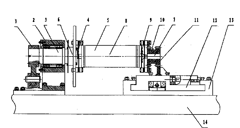
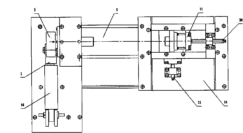
[0048] -Put a pad 13 of the same height under the right support 11, and adjust the axial adjustment screw 20 and the radial adjustment screw 2, so that the left support 2 and the right support 11 are concentric;

[0049] - Install the coupling 5 on the left support 2 and the right support 11 of the test bench. When installing, remove the spring diaphragm 4 at one end of the torque limiter 8 of the coupling 5 so that the output joint of the coupling 5 7 is rigidly connected with the torque limiter 8.

[0050] 2. Test steps:

[0051] A. Set the tightening torque of the torque wrench to 140Nm, tighten the fastening screws 9 on the torque limiter 8, so that the pressing force of each fastening screw 9 is consistent;

[0052] B. Draw an axial scale line on the peripheral surface of the joint of the taper sleeve and the friction flange of the torque lim...

example 2

[0065] Example 2: Maximum load test

[0066] The specific steps of the maximum load test are:

[0067] A. Install the coupling 5 as a whole on the test bench, place a 0.2° wedge-shaped pad 13 between the T-shaped floor-standing table 14 and the supporting plate 12, and make the right support 11 axially tilt; then adjust the diameter Adjust the bolt to make the right support 11 move 12mm in the radial direction of the coupling 5; adjust the axial adjustment bolt to move the right support 11 4mm in the axial direction of the coupling 5, and then lock the right support 11 at T 14 on the floor-standing workbench;

[0068] B. Increase the tightening torque of the wrench by 20Nm on the basis of the slipping torque, and tighten the fastening screw 9 on the torque limiter 8;

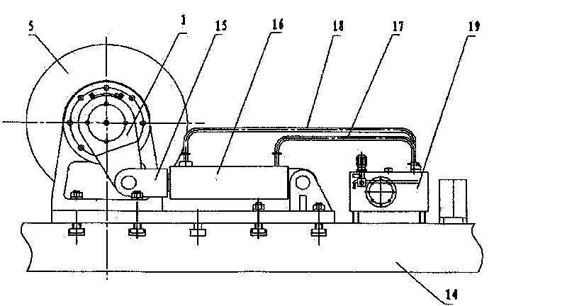
[0069] C. Jog the start button of the hydraulic cylinder 16, and when the output data of the torque sensor 10 reaches the required maximum load, lock the overflow valve 24 of the hydraulic system, keep the sys...


PUM


Abstract

The invention relates to a wind driven generator coupler test-bed and a test method. The test-bed comprises a seat, a driving device and a display; a pair of left bracket and right bracket for installing the coupler is arranged on the seat; the left bracket is a bearing seat and internally provided with a torque input shaft, one end of the shaft is provided with a flange used for butt jointing with the input joint of the coupler; the right bracket is a composed of a torque sensor and a supporting board, the supporting board is arranged on the seat, the torque sensor is fixed on the supporting board and butt joints with the output joint of the coupler; the right bracket is provided with an axial, radial and angular displacement regulating mechanism; the driving device is arranged on the seat and connected with the torque input shaft of the left bracket and drives the shaft to rotate; the torque input shaft is provided with an angle sensor for measuring the angular displacement of the shaft; the display is used for displaying the set parameters and measurement parameters of the test. The invention can be used in test of skid torque calibration and largest load on the wind-electricity coupler.

Description

technical field [0001] The invention relates to a coupling of a wind power generator, in particular to a test bench and a test method for calibrating and detecting the torque of the coupling. Background technique [0002] The speed of the wind turbine propeller is relatively low, so it needs to be connected to the generator after being increased by a gear box, and the output shaft of the gearbox is connected to the main shaft of the generator with a coupling. The coupling has a torque input section and a torque output section with a torque limiter between the input section and the output section. Because the wind speed changes, the input power of the propeller also changes, and the capacity of the generator is determined. Therefore, the coupling adopts a friction slip coupling. When the input power of the propeller is greater than the rated power of the motor, the coupling slips, and the excess energy is converted into friction energy and consumed, thus effectively preventi...

Claims


Application Information

Patent Timeline
Patent Type & Authority Applications(China)
IPC IPC(8): G01L3/00G01M13/00
Inventor 郑谦邱述林贾滨刚陈明东陈福兵宋冬梅梁君
Owner DONGFANG TURBINE CO LTD
Learn More