
Efficient brightening backlight module

A backlight module and high-efficiency technology, which is applied in the field of backlight modules, can solve the problems of poor light directivity and difficulty in improving the brightness of backlight modules, and achieve the effects of improving utilization, brightness and clarity

Inactive Publication Date: 2010-06-09
深圳亚通光电股份有限公司
View PDF0 Cites 6 Cited by
  • Summary
  • Abstract
  • Description
  • Claims
  • Application Information

AI Technical Summary

Problems solved by technology

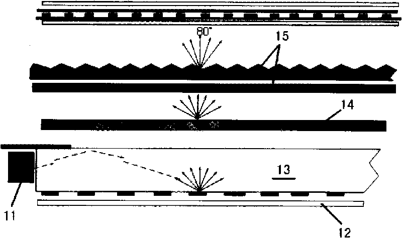
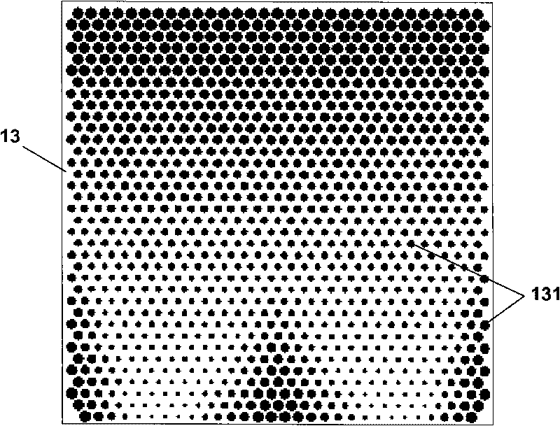
But the shortcoming of this dot production method is that the light directivity is very poor, that is to say, the brightness of the backlight module is difficult to improve.
[0005] Almost all backlight module factories need to purchase light sources and reflective films. Under cost pressure, it is impossible to achieve high brightness by purchasing extremely expensive or nonexistent materials. , in the case of the same level of LED light source brightness, it is an urgent problem to design and develop a super bright backlight module

Method used


Image

  • Efficient brightening backlight module
  • Efficient brightening backlight module
  • Efficient brightening backlight module

Examples


Embodiment Construction

[0027] Below in conjunction with the best embodiment shown in the accompanying drawings, it will be further described in detail.

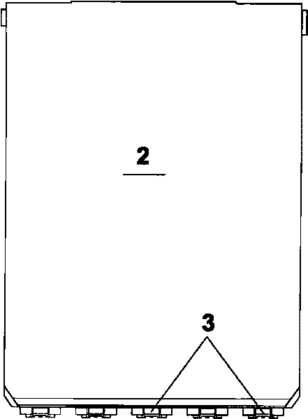
[0028] Such as image 3 As shown, the backlight module of the present invention includes a light guide plate 2 and a light source 3 disposed on one side of the light guide plate 2 . Such as Figure 4 , the six surfaces of the light guide plate 2 are respectively: the vertical side near the light source 3 at the front is the light incident surface 21, the top surface is the light exit surface 22, the bottom surface 23 is close to the reflective film, and the vertical sides of the left and right sides are side surfaces 24 and 25 , and a rear surface 26 opposite to the light-incident surface 21 . The present invention mainly aims to improve the light-incident surface 21 , the light-exit surface 22 , and the bottom surface 23 .

[0029] For convenience of description, such as Figure 4 As shown, we define: take the length direction of the light-inc...


PUM

PropertyMeasurementUnit
heightaaaaaaaaaa
radiusaaaaaaaaaa
heightaaaaaaaaaa

Abstract

An efficient brightening backlight module comprises a light panel (2) and a light source (3) which is arranged on one side of the light panel (2). The upright side of the light panel (2) close to the light source (3) is an incident side (21). An emitting side (22) on the top of the light panel (2) is a parallel convex prism structure which is beneficial to collecting light or reflecting light. A bottom side (23) of the light panel (2) which is back to the emitting side (22) is provided with plurality rows of wedge-shaped dimpling structure which can uniformly derive light from the emitting side (22). The horizontal section of the incident side (21) is small arc saw blade structure which is beneficial to increasing the emitting angle of the incident light on horizontal direction. The backlight module of the invention can greatly increase the lighting efficiency of backlight module and promote the luminance by changing the structure of the top, bottom and incident side of the light panel, and is specially fit for side lighting paster type LED backlight module.

Description

technical field [0001] The invention relates to a backlight module, in particular to a side-emitting patch type backlight module. Background technique [0002] Because the display screen itself of the existing liquid crystal display is a non-luminous display element, the display effect must be achieved by means of a backlight module. Purely in terms of manufacturing cost, the backlight module is also a very important part of the liquid crystal display module. Currently, the light transmittance of a monochrome liquid crystal display (TN type LCD) is 10% to 30%, and that of a color liquid crystal display is only 5% to 8%. The higher the resolution, the clearer the display effect of the color liquid crystal display, the lower the transmittance, such as some high-quality liquid crystal display screens in the development of 3G mobile phones, is only about 2.5%. To achieve the normal 200cd / m of the LCD screen 2 , the brightness of the backlight module must reach 8000cd / m 2 . ...

Claims


Application Information

Patent Timeline
Patent Type & Authority Applications(China)
IPC IPC(8): F21V13/00F21V8/00F21V5/02G02F1/13357F21Y101/02
Inventor 薛峰
Owner 深圳亚通光电股份有限公司
Learn More