High-frequency decoupling piston magneto-rheological damper

A magneto-rheological damper and piston-type technology, applied in the field of dampers, can solve problems such as poor vibration isolation performance and large dynamic stiffness, achieve the effect of reducing high-frequency dynamic stiffness and damping, and improving high-frequency vibration isolation effect

Inactive Publication Date: 2010-06-09
HARBIN INST OF TECH
View PDF0 Cites 10 Cited by
  • Summary
  • Abstract
  • Description
  • Claims
  • Application Information

AI Technical Summary

Problems solved by technology

[0004] The purpose of the present invention is to solve the problem that the magnetorheological damper has poor vibration isolation performance at high frequencies due to its high dynamic stiffness at high frequencies, and provides a high-frequency decoupling piston-type magnetorheological damper damper

Method used


Image

  • High-frequency decoupling piston magneto-rheological damper
  • High-frequency decoupling piston magneto-rheological damper
  • High-frequency decoupling piston magneto-rheological damper

Examples


specific Embodiment approach 1

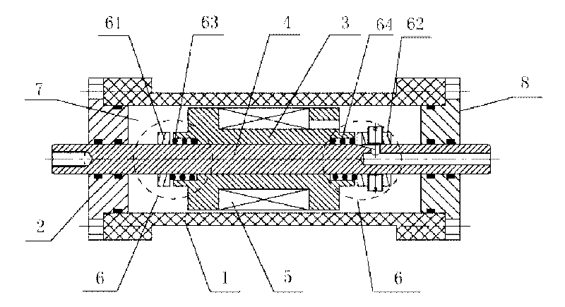
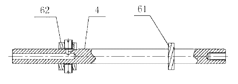
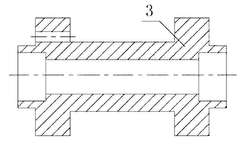
[0008] Specific implementation mode one: combine Figure 1 to Figure 3 Describe this specific embodiment, the high-frequency decoupling piston type magnetorheological damper of this embodiment, which includes a cylinder 1, a first end cover 2, a piston 3, a piston rod 4, a coil 5 and a magnetorheological fluid 7 , it also includes a decoupling mechanism 6, the decoupling mechanism 6 includes a first limit baffle 61, a second limit baffle 62, a first compression spring 63 and a second compression spring 64; the piston rod 4 is cylinder, the central axis of the piston 3 has a cylindrical hole, and both ends of the piston 3 are provided with an annular groove with the central axis of the piston 3 as the central axis, and the two annular grooves of the piston 3 are respectively equipped with The first compression spring 63 and the second compression spring 64, and the diameter of the piston rod 4 is less than or equal to the inner diameter of the first compression spring 63 and th...

specific Embodiment approach 2

[0017] Embodiment 2: Different from Embodiment 1, this embodiment also includes a second end cap 8, which has a cylindrical hole, and the piston rod 4 passes through the second end cap from the cylinder 1. The cylindrical hole on the end cover 8 allows the other end of the piston rod 4 to be placed outside the cylinder barrel 1, and the piston rod 4 is in sealing and sliding contact with the second end cover 8 .

specific Embodiment approach 3

[0018] Embodiment 3: The difference from Embodiment 1 or Embodiment 2 is that the second limiting baffle 62 is fixed to the piston rod 4 through fastening screws.

[0019] In this embodiment, the second limit baffle 62 is detachable, which facilitates the assembly and replacement of the piston 3 and the piston rod 4 .


PUM


Abstract

The invention provides a high-frequency decoupling piston magneto-rheological damper, relating to a damper and solving the problem of poor vibration isolation performance in high frequency caused by great dynamic rigidity of the magneto-rheological damper in high frequency. The high-frequency decoupling piston magneto-rheological damper comprises a cylinder barrel, a first end cover, a piston, a piston rod, a coil, magneto-rheological fluid and a decoupling mechanism, wherein, the decoupling mechanism comprises a first limit baffle, a second limit baffle, a first compression spring and a second compression spring. In high-frequency micro amplitude, the piston rod vibrates in high frequency and micro amplitude, the piston does not move, the piston rod and the piston perform micro relative movement between two limit baffles and no damping exists between the piston rod and the piston; and in low-frequency great amplitude, the piston rod vibrates drastically in low frequency, and the limit baffle pushes the piston to generate great damping. The invention can dramatically lower the high-frequency dynamic rigidity and damping, basically keeps the great damping characteristic of a common magneto-rheological damper, and can be used in the field of isolation vibration.

Description

technical field [0001] The invention relates to a damper. Background technique [0002] Conventional shear-valve magneto-rheological dampers have been widely used in construction, bridges, and machinery. They are mainly used for structural vibration control and consume large externally destructive motion excitations. It can be said that magnetorheological dampers have good performance for damping the vibration of large structures. The combination of magneto-rheological damper and spring can be used as a vibration isolation device for vibration isolation. However, in the field of vibration isolation, the requirements for vibration isolators are often quite special. On the one hand, the vibration isolator should suppress the vibration displacement of the vibration-isolated body, and on the other hand, it should reduce the transmission of the foundation vibration to the vibration-isolated body. The two have opposite requirements on the performance of the vibration isolator: ...

Claims


Application Information

Patent Timeline
Patent Type & Authority Applications(China)
IPC IPC(8): F16F9/53
Inventor 陈照波涂奉臣方勃徐毅坚
Owner HARBIN INST OF TECH
Why Eureka
Try Eureka