
Centralized dust collecting system

A vacuum system and centralized technology, applied in vacuum cleaners, cleaning equipment, household appliances, etc., can solve the problems of high environmental cost, low economic benefit, and severe noise, and achieve low cost, improved cleaning effect, and easy installation.

Inactive Publication Date: 2010-06-09
牛贵胜
View PDF0 Cites 0 Cited by
  • Summary
  • Abstract
  • Description
  • Claims
  • Application Information

AI Technical Summary

Problems solved by technology

As a result, large particles of dust are sucked into the dust bag, and small particles of dust are flying up again, resulting in not only loud noises but also flying dust in the cleaned room.
This "cleaning" disadvantage of high environmental cost and low economic benefit is unavoidable for almost any mobile vacuum cleaner, but it is also undesirable.

Method used


Image

  • Centralized dust collecting system
  • Centralized dust collecting system
  • Centralized dust collecting system

Examples


Embodiment Construction

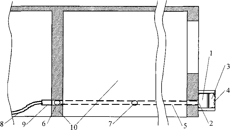
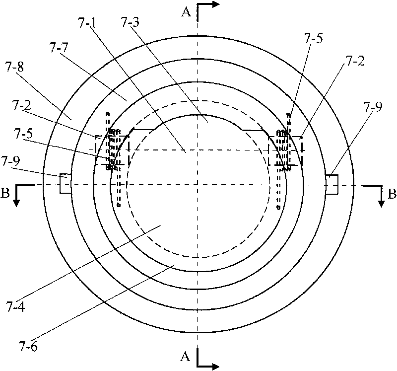
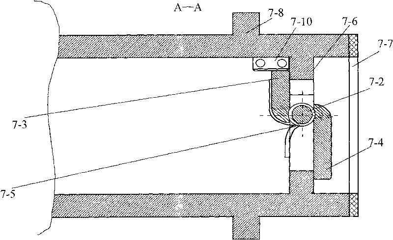
[0017] In the embodiment shown in the drawings, the existing vacuum cleaner main unit (1) is fixedly installed on the outer wall of the room or in a convenient operating position in the open exhaust duct, and the exhaust end is outward; the main dust suction pipe (5) It is fixedly connected with the dust suction port (2) of the main engine, and laid in the wall (10) where it is located. The main dust suction pipe (5) is connected with the dust suction pipes of each room, and the dust suction pipes (6) of the rooms are laid indoors In each partition wall (10), the compartment dust suction pipe (6) has a socket (7) for inserting the terminal dust suction pipe (8) in each compartment; type structure, the valve (7-1) is installed on the air seal limit ring (7-6) through the shaft (7-2), and the shaft (7-2) divides the valve (7-1) into an inner flap ( 7-3) and outward flap (7-4), the springs (7-5) set at the two ends of the shaft (7-2) are used to keep the valve (71) closed reliabl...


PUM


Abstract

The invention discloses a centralized dust collecting system which fixes the existing dust collector host on the outer wall of a room or on the position which is convenient to operate in an opened air vent, and an exhaust end faces outwards; a main dust collecting pipe is fixedly matched with the dust collecting orifice of the host and is laid in the wall body on which the main dust collecting pipe is located; the main dust collecting pipe is matched with each compartmental dust collecting pipe which is laid in each indoor compartmental wall; the compartmental dust collecting pipe is provided with a faucet for inlaying grafting of a terminal dust collecting pipe; the faucet is in a unidirectional air valve inserting and opening structure; meanwhile, a sliding touch power switch is installed and is inserted into a movable terminal dust collecting pipe so as to be communicated with an airflow channel; the power supply is switched on, and the faucet in which the terminal dust collecting pipe is not inserted keeps the state that the airflow channel is closed; one end of the movable terminal dust collecting pipe is manufactured into the adaptive structure of the unidirectional air valve inserting and opening faucet, and the other end is manufactured into the adaptive structure which can be assembled to various dust collecting nozzles and brushes.

Description

Technical field [0001] The invention relates to an installation and application method of indoor cleaning equipment. Background technique [0002] At present, the known cleaning equipment-vacuum cleaner can only be used indoors as a whole, and the system airflow is in a closed cycle indoors. In this way, even if the gap of the dust bag filter on the main unit of the vacuum cleaner is small, there will be dust flying out under the strong air pressure. As a result, large particles of dust are sucked into the dust bag, and small particles of dust are flying up again, causing not only loud noises but also fine dust flying in the cleaned room. This "cleaning" disadvantage of high environmental cost and low economic benefit is unavoidable for almost any mobile vacuum cleaner, but it is also undesirable. Therefore, it is urgent to take a measure that can overcome this disadvantage, develop an economical and efficient indoor cleaning method, and develop a fixed centralized dust co...

Claims


Application Information

Patent Timeline
Patent Type & Authority Applications(China)
IPC IPC(8): A47L5/36A47L5/38
Inventor 屈百达
Owner 牛贵胜
Learn More