
Liquid electrolyte battery with electrolyte mixing by convection current

A liquid electrolyte and electrolyte technology, which can be used in large-sized batteries/batteries, small-sized batteries/batteries, transfer electrolyte devices, etc., which can solve the problems that batteries cannot reach full power and reduce battery life.

Inactive Publication Date: 2010-06-02
IQ POWER LICENSING
View PDF3 Cites 6 Cited by
  • Summary
  • Abstract
  • Description
  • Claims
  • Application Information

AI Technical Summary

Problems solved by technology

As a result, the electrode plates are corroded at locations where the acid concentration is too high, which reduces the life of the battery, and the battery cannot reach its full power at electrode locations where the acid concentration is too low

Method used


Image

  • Liquid electrolyte battery with electrolyte mixing by convection current
  • Liquid electrolyte battery with electrolyte mixing by convection current
  • Liquid electrolyte battery with electrolyte mixing by convection current

Examples


Embodiment Construction

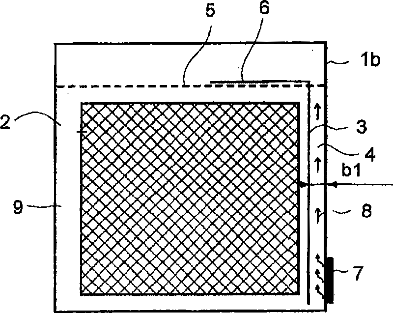
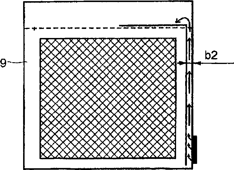
[0028] Figure 5 A battery box with 6 cells is shown. However, all of the following descriptions refer only to a single cell, which is in the Figure 1a with 1b in accordance with Figure 5 The sectional view of the 1c direction is shown. Because the cell is also an independent battery, only the battery is discussed below, because the present invention can be used not only for a single cell, but also for a combination of multiple cells.

[0029] according to Figure 1a A flow channel plate 3 is arranged between the vertical housing wall 1 b and the side edges of the electrode plates 2 , so that a flow channel 4 is formed between the flow channel plate 3 and the housing wall 1 b. The upper edge of the flow channel plate 3 is located in the region of the electrolyte level 5 and is connected to a drain plate 6 which extends parallel to the upper edge of the electrode plate 2 towards the center of the housing. In the region of the lower end section of the flow channel 4 , a re...


PUM


Abstract

The invention relates to a liquid electrolyte battery, such as, for example, a lead-acid battery, which is, for example, used as a starter battery in vehicles. A thermal liquid electrolyte circulating device is provided on at least one side of the battery and has a cross-section that is optimized with respect to its flow properties.

Description

technical field [0001] The invention relates to a liquid electrolyte battery, such as a lead-acid battery, which is used in vehicles, for example as a starter battery. Background technique [0002] Efforts towards lightweight construction in the automotive industry also involve reductions in battery weight. At the same time, the demands on battery power are also increasing, because in addition to the conventional energy used to start e.g. small cars, additional equipment such as electric window lifters, for seat adjustment or also for electric heating are required The seat's servo motor provides energy. In addition, it is desirable that the battery power be kept at a constant high level as much as possible over the entire lifetime of the battery, since this also enables electrical control of safety-relevant functional units such as steering and braking and operation. The battery capacity is to be understood as meaning the capacity of the battery and the capacity of the ba...

Claims


Application Information

Patent Timeline
Patent Type & Authority Applications(China)
IPC IPC(8): H01M2/02H01M2/38H01M10/42H01M10/50H01M10/06H01M50/102H01M50/103
CPCH01M10/5083Y02E60/12H01M2/024H01M10/5016H01M2/38H01M10/5032H01M10/06H01M10/5006H01M10/4214H01M10/625H01M10/615H01M10/647H01M10/6571Y02E60/10H01M50/70H01M50/102H01M50/103
Inventor C·G·鲍尔S·奇尔克
Owner IQ POWER LICENSING
Learn More