Drive pulleys

A technology for driving pulleys and motors, used in belts/chains/gears, transmissions, electric components, etc., and can solve different problems

Inactive Publication Date: 2010-06-02
NEXXTDRIVE LTD
View PDF2 Cites 12 Cited by
  • Summary
  • Abstract
  • Description
  • Claims
  • Application Information

AI Technical Summary

Problems solved by technology

Of course, this prior art document refers to a drive hub rather than a drive pulley, and the considerations for the two assemblies are quite different

Method used


Image

  • Drive pulleys
  • Drive pulleys
  • Drive pulleys

Examples


Embodiment Construction

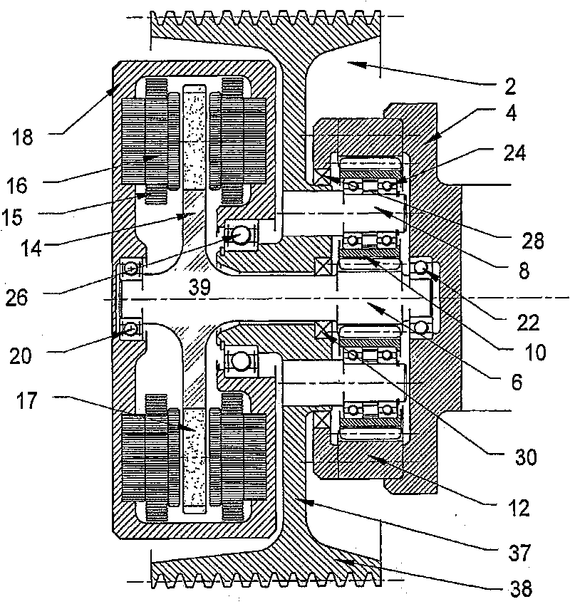
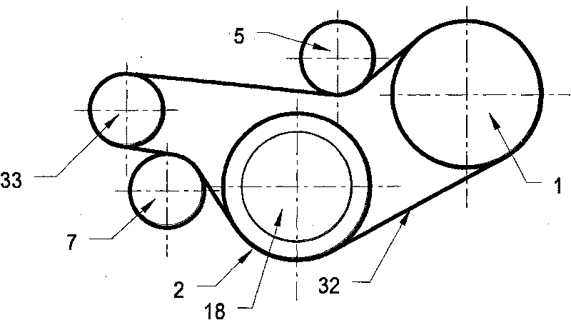
[0025] See first figure 1 , image 3 with Image 6 , The pulley shown is shown connected to one end of the crankshaft 4 of the transversely mounted engine 80 of the front-engine car. The crankshaft 4 is connected to the input end of a transmission system including a planetary gear set, and the output end of the transmission system is connected to the pulley member 2 including radial spokes 37 connected to the free edge portion of the pulley member 2 The free edge portion is a hollow cylindrical member 38, the outer circumferential surface of the cylindrical member 38 is provided with a plurality of V-shaped grooves, and constitutes the driving belt engaging surface of the multi-groove V-belt wheel.

[0026] The planetary gear set includes a sun gear 6 which constitutes an extension of a rotatable central shaft 39. The sun gear meshes with two or more planetary gears 10, which are mounted on respective planetary shafts 8 through corresponding bearings 24 inserted so as to be able...


PUM


Abstract

A drive pulley, particularly for automotive auxiliary equipment, includes an input for connection to an engine (80) and an output. One of the input and output comprises a hollow cylindrical member (38) whose outer surface constitutes a pulley belt engagement surface. The input and output are connected by a transmission system including an epicyclic gearset. The planet shafts (8) are connected to a common carrier (37). The system further includes two electric motor / generators, the rotors (14, 90) of which are connected to the output and a sun gear (6), respectively, the electrical connections on the stators (16, 94) of which are connected to a controller (85) arranged selectively to control the flow of electrical power between them. The transmission is at least partially accommodated within the hollow cylindrical member (38). The input is connected to an annulus gear (12) and the output is connected to the carrier (37). At least one of the motor / generators is remote from the hollow cylindrical member (38) and the gearset is at least partially accommodated within the hollow cylindrical member (38).

Description

Technical field [0001] The present invention relates to a driving pulley for automotive accessory equipment and internal combustion engine accessory equipment, such as a cooling fan, an oil pump, an air-conditioning pump and other accessory equipment. Specifically, the present invention relates to a driving pulley of the following type, which includes an output The input end and the input end for connecting with the engine, one of the input end and the output end includes a hollow cylindrical member, the outer surface of the cylindrical member constitutes a transmission belt engagement surface, the input end and the output end are connected by a transmission system, the The transmission system includes a planetary gear set, the planetary gear set includes two or more planetary gears, the two or more planetary gears are carried by respective planetary bearings to rotate around the axis of the planetary shaft, and are connected with the sun gear and The other member is engaged, th...

Claims


Application Information

Patent Timeline
Patent Type & Authority Applications(China)
IPC IPC(8): F16H3/72H02K7/10H02K7/116
CPCH02K7/116H02K7/1008H02K21/24F16H3/724
Inventor F·H·莫勒
Owner NEXXTDRIVE LTD
Why Eureka
Try Eureka