
Method for continuously and dynamically removing iron from minerals

A mineral and dynamic technology, applied in chemical instruments and methods, magnetic separation, solid separation, etc., can solve the problems of difficulty in giving magnetic field strength parameters, low efficiency (need to stop to pick up iron, high labor intensity, etc., to achieve low cost Effect

Inactive Publication Date: 2010-06-02
KUNMING UNIV OF SCI & TECH
View PDF5 Cites 3 Cited by
  • Summary
  • Abstract
  • Description
  • Claims
  • Application Information

AI Technical Summary

Problems solved by technology

Most of the existing belt conveyor iron removal technology adopts the method of installing an iron removal device above the conveyor belt. When this method is used to process ores containing magnetic minerals, because the ores on the general conveyor belt have a certain accumulation thickness and uneven lumpiness, Therefore, even if the electromagnet with adjustable magnetic field strength is used to remove iron, it will inevitably bring up a lot of ores, and the recovery of these ores requires a more complicated system to complete; Low (need to stop to pick up iron), poor reliability (requires manual visual identification of iron parts) and high labor intensity
The computer-controlled multi-stage electromagnet magnetic field strength step-by-step iron removal system solves the above problems to a certain extent, but there are still two main shortcomings: one is that it cannot guarantee that the iron that needs to be removed when the last stage electromagnet is working The iron pieces are always located on the surface of the ore pile on the conveyor belt (especially when the size of the iron pieces is small), so even if computer control is used, it is difficult to give the appropriate magnetic field strength parameters at this level to ensure that no ore is entrained; the second is the system Large investment in equipment

Method used


Image

  • Method for continuously and dynamically removing iron from minerals

Examples


Embodiment Construction

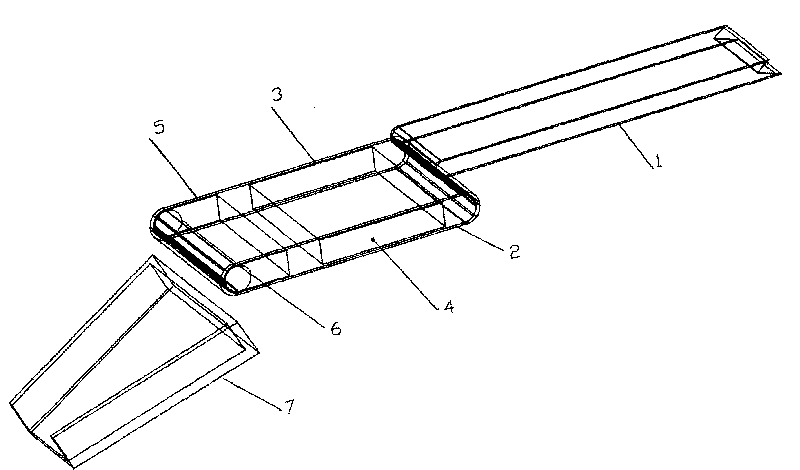
[0011] see figure 1 , the auxiliary conveyor belt 2 is placed under the unloading end of the main conveyor belt 1 to accept the ore unloaded by the main conveyor belt 1. The auxiliary conveyor belt 2 is functionally divided into two sections, namely the vibration paving section 3 and the magnet adsorption section 5. First, vibrate the piled ore on the auxiliary conveyor belt 2 through the exciter 4. The length of the vibrating paving section depends on the amount of ore conveyed and the excitation parameters of the exciter 4. The parameter selection range is; followed by the magnet The magnetic field strength of the adsorption section 5 and the magnet group 6 depends on the magnetic properties of ferromagnetic minerals and other factors. The amplitude is 1mm-10mm, and the frequency is 5Hz-50Hz; Blocks (or grains) on it can directly contact with the belt surface of the auxiliary conveyor belt 2. The magnets installed on the auxiliary conveyor belt are permanent magnets or elec...


PUM


Abstract

The invention provides a method for continuously and dynamically removing iron from magnetic mineral ores. The invention belongs to a method for ore sorting, in particular to a method for continuously and dynamically removing iron from the magnetic mineral ore. The method comprises the following steps that: the lower part of a discharge end of an ore main conveying belt is provided with a segment of auxiliary conveying belt, and ore block on the front segment of the auxiliary conveying belt is paved by vibration, so that both of the ore block and the iron which is possibly mixed in the ore block can be directly contacted with the surface of the auxiliary conveying belt; and the lower part of the back segment of the discharge end of the auxiliary conveying belt is provided with a magnet, so that the ores can be discharged from the end part, and the iron can be conveyed to a position away from the magnet along with the auxiliary conveying belt, and then discharged. The equipment has a simple structure, and the dynamical and continuous removal of the iron from the ores containing the magnetic minerals can be easily achieved in lower cost under a condition of no ores mixed in the sorted iron.

Description

technical field [0001] The invention belongs to a method for ore separation, in particular to a method for dynamically and continuously removing iron pieces from ore containing magnetic minerals (such as magnetite, vanadium-titanite, etc.) without entraining the ore. Background technique [0002] In the process of ore mining, it is unavoidable that various iron pieces are mixed into the ore, and before sorting the useful minerals in the ore, most of the ore needs to be crushed first. A small amount of iron mixed in the ore will affect the normal operation of the crusher, so it is usually removed before the ore enters the crusher. Most of the existing belt conveyor iron removal technology adopts the method of installing an iron removal device above the conveyor belt. When this method is used to process ores containing magnetic minerals, because the ores on the general conveyor belt have a certain accumulation thickness and uneven lumpiness, Therefore, even if the electromagn...

Claims


Application Information

Patent Timeline
IPC IPC(8): B03C1/22
Inventor 张成良李心一
Owner KUNMING UNIV OF SCI & TECH
Learn More