Eureka AIR delivers breakthrough ideas for toughest innovation challenges, trusted by R&D personnel around the world.

Electromagnetic system for detecting distance between adjacent wells while drilling

A technology of electromagnetic detection and electromagnetic measurement, which is applied in the fields of electric/magnetic detection for logging records, magnetic field measurement and measurement using the principle of magnetic flux control, and can solve the problem of confidentiality, monopoly of core technology, and difficulty in meeting complex structure wells. and other problems, to achieve the effect of convenient use, high-precision guiding effect and simple structure

Active Publication Date: 2010-05-26
CHINA UNIV OF PETROLEUM (BEIJING)
View PDF6 Cites 44 Cited by
  • Summary
  • Abstract
  • Description
  • Claims
  • Application Information

AI Technical Summary

Problems solved by technology

At present, the measurement-while-drilling tools commonly used in China cannot directly measure the distance between adjacent wells, so it is difficult to meet the special requirements of detection-while-drilling for the distance between adjacent wells in wells with complex structures
In addition, although foreign countries have developed an electromagnetic guidance system while drilling that can basically meet the above requirements, its core technology is still kept secret and monopolized.

Method used


Image

  • Electromagnetic system for detecting distance between adjacent wells while drilling
  • Electromagnetic system for detecting distance between adjacent wells while drilling
  • Electromagnetic system for detecting distance between adjacent wells while drilling

Examples


Embodiment Construction

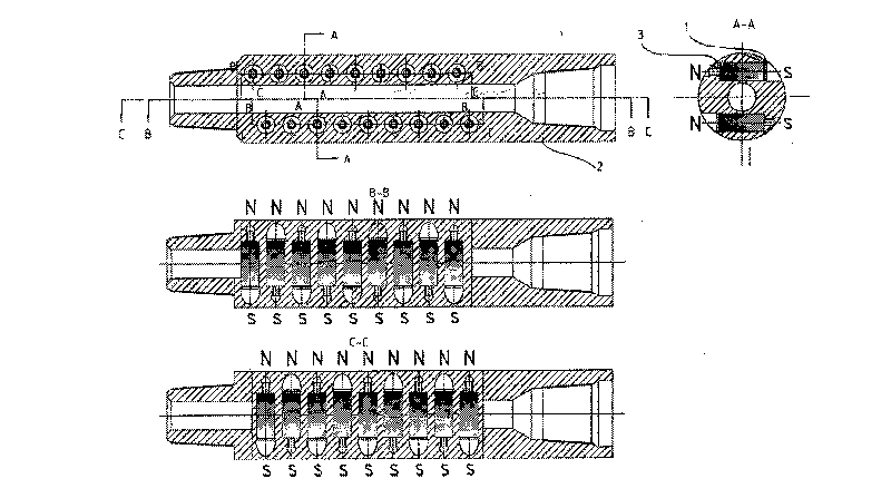
[0036] The magnetic short section of the present invention will be described below with reference to the accompanying drawings and embodiments.

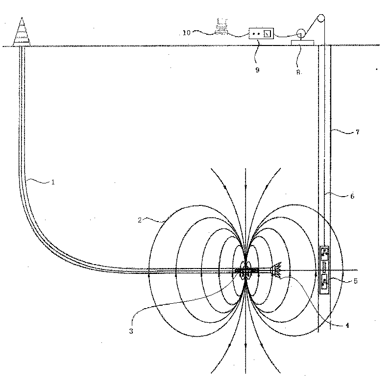
[0037] like figure 1 As shown, the hardware of the electromagnetic guidance system consists of the magnetic sub, the probe tube, the surface system and the drawworks. The magnetic sub and the drill bit are mounted together as the drill bit is run into the horizontal well. The magnetic sub is not only a part of the drill string, but also the signal source of the electromagnetic guidance system. During operation, the magnetic sub is usually installed on the drill collar closest to the drill bit. During the drilling process, the position of the magnetic sub can be approximated. that is the position of the drill bit. The probe pipe is lowered into a pre-drilled vertical well through a winch with a wire cable. The position of the probe pipe in the vertical well is that the axial center of the probe pipe is 1.5 meters above the intersecti...


PUM


Abstract

The invention provides an electromagnetic system for detecting a distance between adjacent wells while drilling, which is capable of providing accurate guide measurement and calculation for the control of well tracks of wells with complex structures, such as a cross well, a U-shaped communicated well, a dual-horizontal well, an accident rescue well and the like. The electromagnetic system for detecting the distance between adjacent wells while drilling mainly comprises a magnetic pipe nipple, an electromagnetic measuring instrument and a method for calculating the distance between adjacent wells, wherein the magnetic pipe nipple is a hollow cylinder with API standard ports at the two ends consisting of a non-magnetic drill collar and a plurality of permanent magnets, and is used as a signal source for an electromagnetic guide system; the measuring instrument mainly comprises an underground searching tube and a ground system, and is mainly used for detecting a magnetic vector signal ofthe magnetic pipe nipple and for sending data to a computer through an RS-232 interface; and the computer processes and analyzes measured information by using the method for calculating the distance between adjacent wells so as to convert the measured information of a drill position into readable data for engineers. The electromagnetic system for detecting the distance between adjacent wells while drilling has a simple structure and convenient use, and provides an effective high and new technological measure for the detection and control of the distance between adjacent wells with complex structures.

Description

technical field [0001] The invention relates to an electromagnetic detection system while drilling the distance between adjacent wells, belonging to the technical field of underground resource drilling and production engineering. The invention is mainly composed of a magnetic sub, an electromagnetic measuring instrument and an adjacent well distance measurement and calculation method. Background technique [0002] In the exploitation of oil, natural gas and coalbed methane, the drilling trajectories of complex structure wells such as double horizontal wells, connecting wells and U-shaped wells are complex, and the directional control is difficult, requiring accurate detection of the distance between adjacent wells while drilling. At present, the commonly used measurement-while-drilling tools in China cannot directly measure the distance of adjacent wells, so it is difficult to meet the special requirements of detection while drilling the distance of adjacent wells in complex...

Claims


Application Information

Patent Timeline
Patent Type & Authority Applications(China)
IPC IPC(8): E21B47/00E21B47/12E21B17/16E21B47/06G01V3/18G01R33/04G01V7/00E21B47/0228E21B47/092E21B47/13
Inventor 高德利孙东奎吴志永刁斌斌闫永维
Owner CHINA UNIV OF PETROLEUM (BEIJING)
Why Eureka
Eureka Blog
Learn More