Switching device of optical fiber for imaging sensor

An imaging sensor, filter switching technology, used in optics, instruments, image communication and other directions, can solve the problems of not being able to be used in places with high reliability requirements, the effect is not obvious, and the driving force is not enough, and the switching process is accurate and fast. Solve the effect of unstable switching technology and easy assembly

Inactive Publication Date: 2011-03-16
深圳市卡美特电子技术有限公司
View PDF0 Cites 0 Cited by
  • Summary
  • Abstract
  • Description
  • Claims
  • Application Information

AI Technical Summary

Problems solved by technology

The disadvantage of this driving conversion method is that the driving force is not enough, and it can only drive filters below 0.6mm thick
The effect is not obvious, and it is often not in place, so it cannot be used in places with high reliability requirements

Method used


Image

  • Switching device of optical fiber for imaging sensor
  • Switching device of optical fiber for imaging sensor
  • Switching device of optical fiber for imaging sensor

Examples


Embodiment Construction

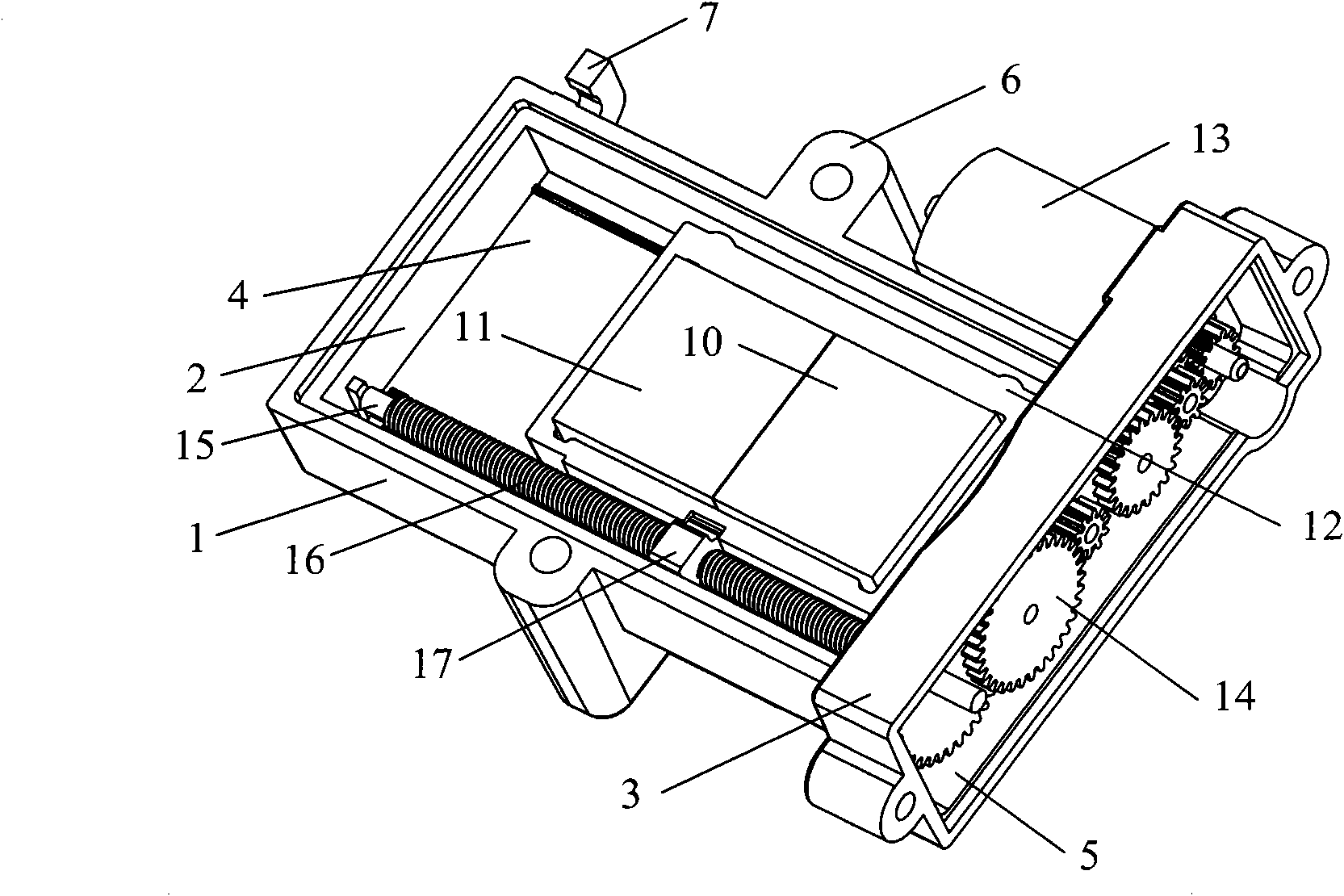
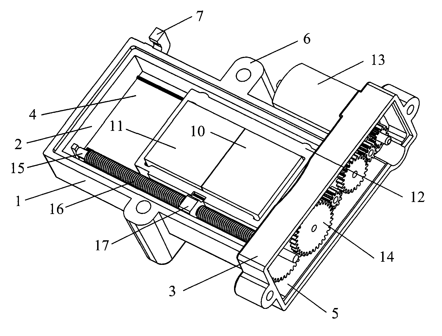
[0027] The optical filter switching device for an imaging sensor provided by the invention can be applied to video cameras, DVs, digital cameras and other equipment.

[0028] The optical filter switching device for an imaging sensor provided by the present invention is composed of three parts, including a housing 1, a sliding unit and a driving unit. Wherein, the sliding mechanism and the driving mechanism are arranged inside the casing 1 respectively, and the driving mechanism is arranged at the upper end or the lower end of the sliding mechanism. The housing 1 is composed of an accommodating part 2 and a deceleration box body 3, the accommodating part 2 is connected with the deceleration box body 3, and a moving device accommodating cavity 4 and a decelerating accommodating cavity 5 are respectively provided inside the accommodating part 2 and the decelerating box body 3, The moving device accommodating cavity 4 and the decelerating accommodating cavity 5 are mainly used for...


PUM


Abstract

The invention relates to a switching device of an optical fiber for an imaging sensor, comprising a shell, a sliding mechanism and a drive mechanism. The shell consists of an accommodating part and a reduction gearbox body; the sliding mechanism consists of a lead screw, a lead screw sleeve ring and a fixed frame of the optical fiber; and the drive mechanism consists of a motor and a gear set. One end of a motor and one end of the sliding mechanism are respectively connected with the gear set; the sliding mechanism is arranged in an accommodating cavity of a mobile device, and the gear set isarranged in a deceleration accommodating cavity; and the sliding mechanism consists of the lead screw and the lead screw sleeve ring, and the lead screw sleeve ring is clamped at the edge of the fixed frame of the optical fiber. The invention has reasonable design structure, smart and flexible volume, accurate and rapid switching process, low error ratio and easy assembly, and can effectively solve the problem of unstable switching technology of the traditional double-optical fiber, such that the optical fiber can realize accurate positioning in the switching process, and rays can be sufficiently utilized to greatly improve the performance of a camera.

Description

technical field [0001] The invention relates to an optical filter switching device, in particular to an optical filter switching device for an imaging sensor which is accurate and fast in the switching process and can be applied to a digital image shooter or a video camera. The optical filter switching device for an imaging sensor provided by the invention can be applied to video cameras, DVs, digital cameras and other equipment. Background technique [0002] Due to the obvious difference in light brightness between day and night, two filters with different functions are usually used in day or night. In the daytime, because the light contains various invisible light that interferes with the imaging of the imaging sensor, color shift occurs. of light. But at night, the original light energy is insufficient. At this time, the filter should be removed to allow all the light to come in, but a piece of fully transparent glass should be used to correct the focus deviation caused...

Claims


Application Information

Patent Timeline
Patent Type & Authority Patents(China)
IPC IPC(8): G03B17/14H04N5/225
Inventor 成秋庚曾小山
Owner 深圳市卡美特电子技术有限公司
Why Eureka
Try Eureka