Power driving distribution method of moving iron type planar motor coil array

A planar motor and coil array technology, applied in motor control, electrical components, control systems, etc., can solve the problems of increasing cable movement interference, increasing the number of drives, and inconvenient motors, so as to reduce the number of power drives and realize large-stroke motion. cost saving effect

Active Publication Date: 2010-05-12
TSINGHUA UNIV +1
View PDF3 Cites 17 Cited by
  • Summary
  • Abstract
  • Description
  • Claims
  • Application Information

AI Technical Summary

Problems solved by technology

For moving-coil planar motors, since it is necessary to provide power to the moving coils and equip a cooling system, it is necessary to connect cables to the mover, which brings great inconvenience to the structural design and the work of the motor. Increase the movement interference of the

Method used


Image

  • Power driving distribution method of moving iron type planar motor coil array
  • Power driving distribution method of moving iron type planar motor coil array
  • Power driving distribution method of moving iron type planar motor coil array

Examples


Embodiment

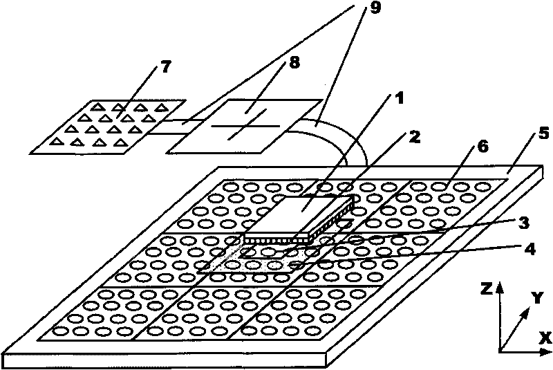
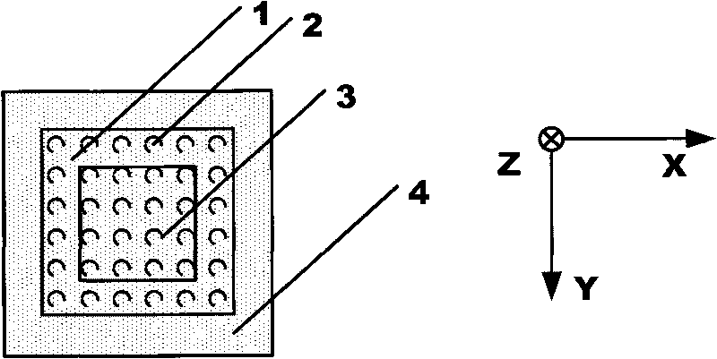
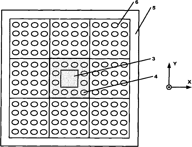
[0046] refer to figure 1 , 4. Taking the movement of the mover 1 along the X-axis direction as an example, the transition process of the driving distribution state of the mover 1 during the movement is demonstrated, so as to further understand the present invention.

[0047] The maximum speed V of the mover 1 movement max =1m / s, the maximum switching time T=0.1ms for the stator coil array 6 to turn on or off the driver through the switch device 8, according to the calculation formula of the width of the square transition state area 4 L≥V max *T, take L=30mm.

[0048] Under the premise of ensuring that the electromagnetic interaction between the covering coil under the mover magnetic steel array 2 and the magnetic steel array will not produce edge effects, the maximum size of the outer periphery of the covered coil is taken as the working state area 3, that is, the side length of the working state area 3 is 60mm. The frame in the transition state area is consistent with the s...


PUM


Abstract

The invention relates to a power driving distribution method of a moving iron type planar motor coil array. The method comprises the following steps: dividing a square stator coil array of the moving iron type planar motor into n*n dividing areas, dividing each dividing area into a work state area and a transitional state area, and determining the total quantity of power drivers according to the quantity of coils in each dividing area, and forming a driver array; and connecting the driver array with the stator coil array by switch equipment, and guaranteeing that each driver is connected with the coil at a corresponding position in each dividing area by the switch equipment. According to the position of a rotor magnetic steel array, the power driving distribution method determines the range of action of the coil array, uses the limitation of the transitional state area to control the on-off and the current of the coils, and realizes large-stroke planar vector movement of a rotor. The power driving distribution method can solve the problems of complex structure and extremely high total cost of the driver equipment, resulting from excessive quantity of the drivers due to excessive quantity of the stator coils.

Description

technical field [0001] The invention relates to a connection method between a moving iron planar motor coil array and a driver, in particular to a driver distribution method. Background technique [0002] With the development of advanced manufacturing technology, some precision control equipment such as lithography machines need to perform precise motion control in an approximately flat space, and such high-precision motion is realized by ultra-precision planar motors. The planar motor has the characteristics of two-dimensional direct drive, which can realize the following movements: large-stroke movement in the horizontal degree of freedom X and Y directions, which is used to realize fast stepping and precise scanning of the wafer; small movement in the vertical degree of freedom Z direction ; Tiny rotations around the three coordinate axes X, Y, and Z are used to achieve leveling and focusing. Therefore, it has broad application prospects in two-dimensional plane position...

Claims


Application Information

Patent Timeline
IPC IPC(8): H02P31/00H02N15/00
Inventor 朱煜胡金春张鸣廖凯杨开明尹文生徐登峰汪劲松段广洪
Owner TSINGHUA UNIV
Why Eureka
Try Eureka