Heat exchanger and its fins, and heat exchange device including the heat exchanger

A technology of heat exchangers and fins, applied in the field of heat exchangers, can solve the problems of many refrigerant passages, poor heat transfer performance, and low refrigerant flow rate

Active Publication Date: 2011-12-21
SANHUA(HANGZHOU) MICRO CHANNEL HEAT EXCHANGER CO LTD
View PDF0 Cites 1 Cited by
  • Summary
  • Abstract
  • Description
  • Claims
  • Application Information

AI Technical Summary

Problems solved by technology

[0007] First, the header 3' is relatively long, so the manufacturing cost is relatively high;
[0008] Second, the header 3' is longer, so it is more difficult to distribute the refrigerant evenly;
[0010] Fourth, the number of flat tubes 2' is large, that is, there are many refrigerant passages, the flow rate of refrigerant in the flat tubes 2' is low, and the heat transfer performance is poor
[0013] image 3 The flat tubes 2' of the shown elongated heat exchanger are arranged horizontally, thus solving the four problems caused by the vertical arrangement of the above-mentioned flat tubes 2', but in this way, if the conventional fins 1 are still used ’ design, it will bring about the problem of condensed water removal. It has been proved by experiments that the condensed water will be caught by the flat tube 2’ arranged horizontally, and a large part of the condensed water will gather at the trough of the wave-shaped fin 1’

Method used


Image

  • Heat exchanger and its fins, and heat exchange device including the heat exchanger
  • Heat exchanger and its fins, and heat exchange device including the heat exchanger
  • Heat exchanger and its fins, and heat exchange device including the heat exchanger

Examples


Embodiment Construction

[0041] The core of the present invention is to provide a fin used in a heat exchanger, the fin has a high drainage performance; another core of the present invention is to provide a heat exchanger comprising the fin; another aspect of the present invention The core is to provide a heat exchange device including the heat exchanger.

[0042] In order to enable those skilled in the art to better understand the technical solutions of the present invention, the present invention will be further described in detail below in conjunction with the accompanying drawings and specific embodiments.

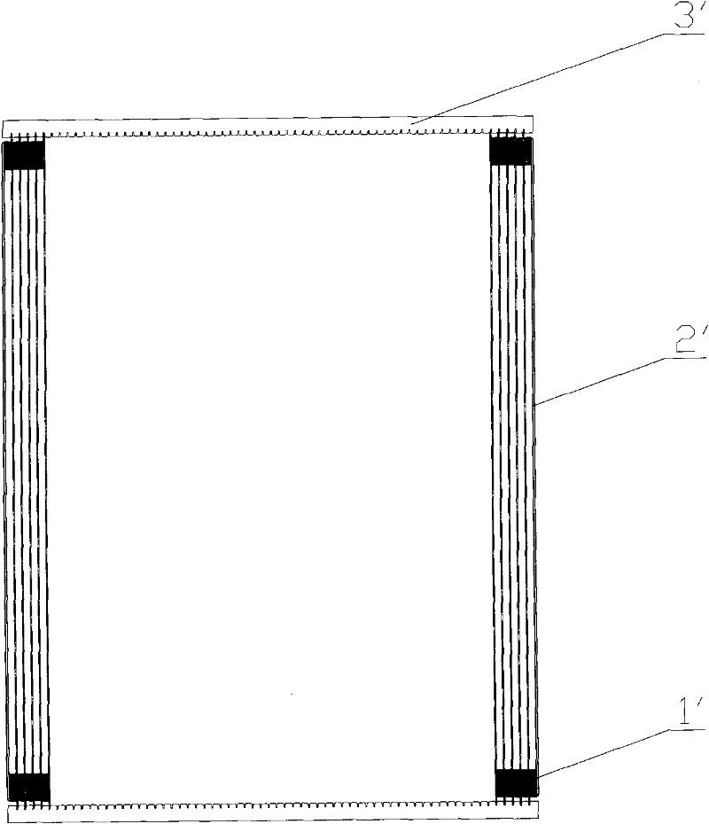
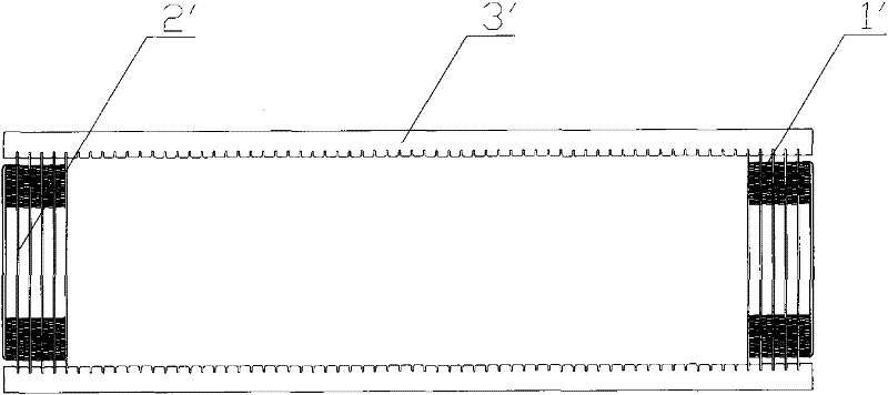
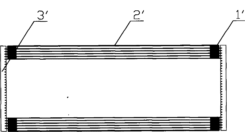
[0043] Please refer to Figure 5 and Image 6 , Figure 5 It is a schematic diagram of the front structure of the fin in an embodiment of the present invention; Image 6 It is a right-view structure diagram of fins in an embodiment of the present invention.

[0044] In the first embodiment, the fin provided by the present invention is used in a microchannel heat exchanger, and the microcha...


PUM


Abstract

The invention discloses a fin used in a microchannel heat exchanger. The heat exchanger includes a plurality of substantially horizontally arranged flat tubes (2), and the fin is fixedly connected to two adjacent flat tubes. between the tubes (2), and extend in the form of wavy lines along the axial direction of the flat tube (2); Outlet (1); the trough (11) of the fin extension (1) is provided with a channel for draining condensed water, and the fin has high drainage performance. In addition, the invention further discloses a heat exchanger comprising the fins. Furthermore, the invention also discloses a heat exchange device comprising the heat exchanger.

Description

technical field [0001] The invention relates to the technical field of heat exchangers, in particular to a fin used in a heat exchanger; the invention also relates to a heat exchanger comprising the fin; the invention also relates to a heat exchanger comprising the heat exchanger swap device. Background technique [0002] During the operation of parallel flow / micro-channel evaporator, condensed water will be generated on the surface, which will affect the heat transfer performance of the heat exchanger and the flow performance of the air. [0003] Please refer to figure 1 , figure 1 Schematic diagram of a typical heat exchanger in the prior art. [0004] In order to improve the drainage performance of the micro-channel evaporator, it is generally necessary to set the flat tube 2' of the micro-channel heat exchanger vertically, and at this time the header 3' is set horizontally, as shown in figure 1 Shown; It is verified by experiments that this arrangement of flat tubes ...

Claims


Application Information

Patent Timeline
Patent Type & Authority Patents(China)
IPC IPC(8): F28F3/02
Inventor 蒋建龙斯蒂芬·艾贝尔安德鲁B·缪塞尔菲斯蒂格·彼洋
Owner SANHUA(HANGZHOU) MICRO CHANNEL HEAT EXCHANGER CO LTD
Why Eureka
Try Eureka