Condensate water recovery device for condenser

A technology of recycling device and condensate water, applied in lighting and heating equipment, etc., to achieve the effect of saving gas cost, saving fuel, smooth and reasonable process

Inactive Publication Date: 2008-07-09
北京东方上达节能设备有限公司
View PDF4 Cites 0 Cited by
  • Summary
  • Abstract
  • Description
  • Claims
  • Application Information

AI Technical Summary

Problems solved by technology

[0006] The purpose of the present invention is to provide a condensed water recovery device for a condenser to solve the problem of timely discharge of condensed water in a condenser with a discharge structure from the lower part of the condenser when the flue is installed from the bottom to the top. to increase the efficiency of the condenser

Method used


Image

  • Condensate water recovery device for condenser
  • Condensate water recovery device for condenser

Examples


Embodiment Construction

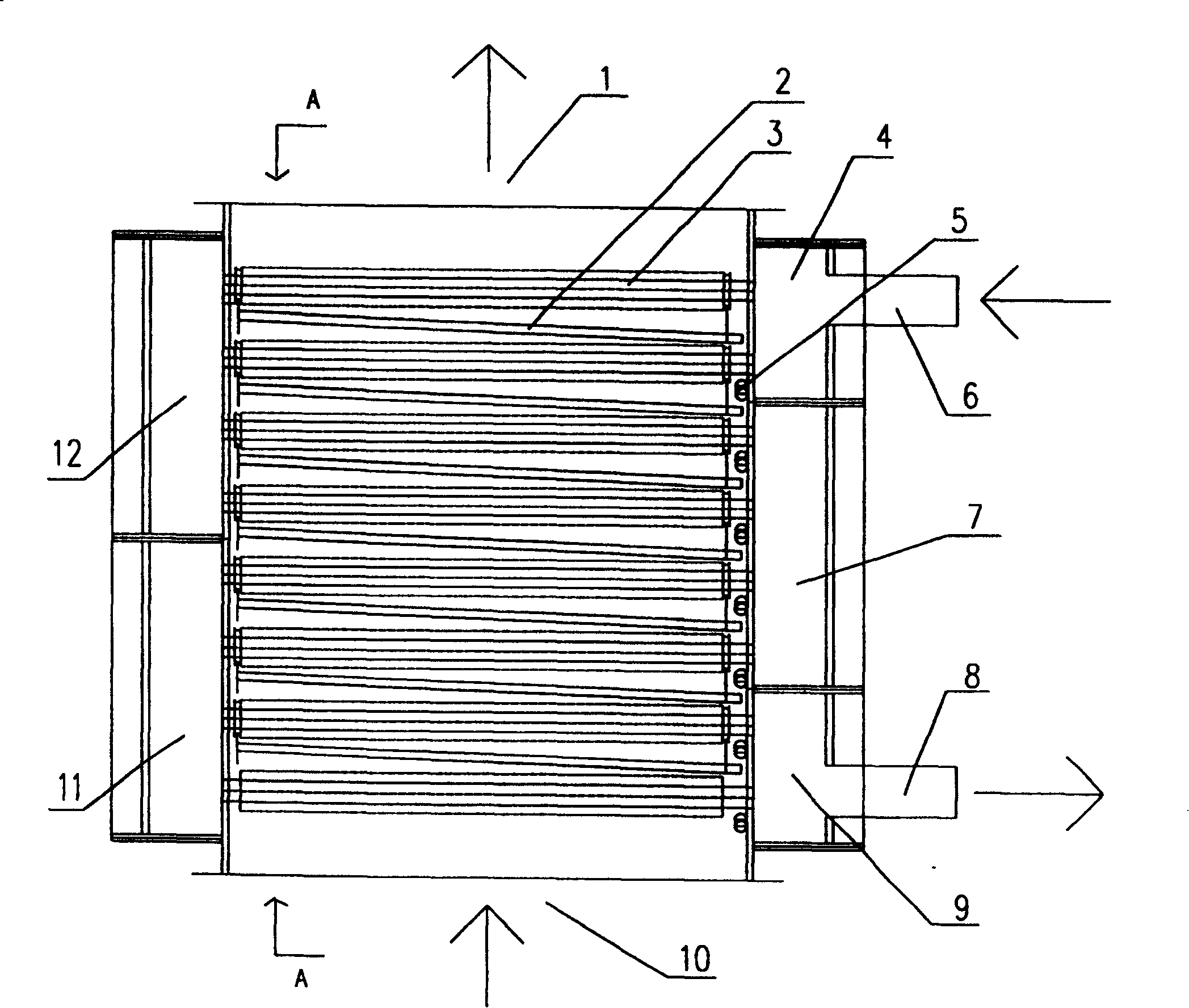
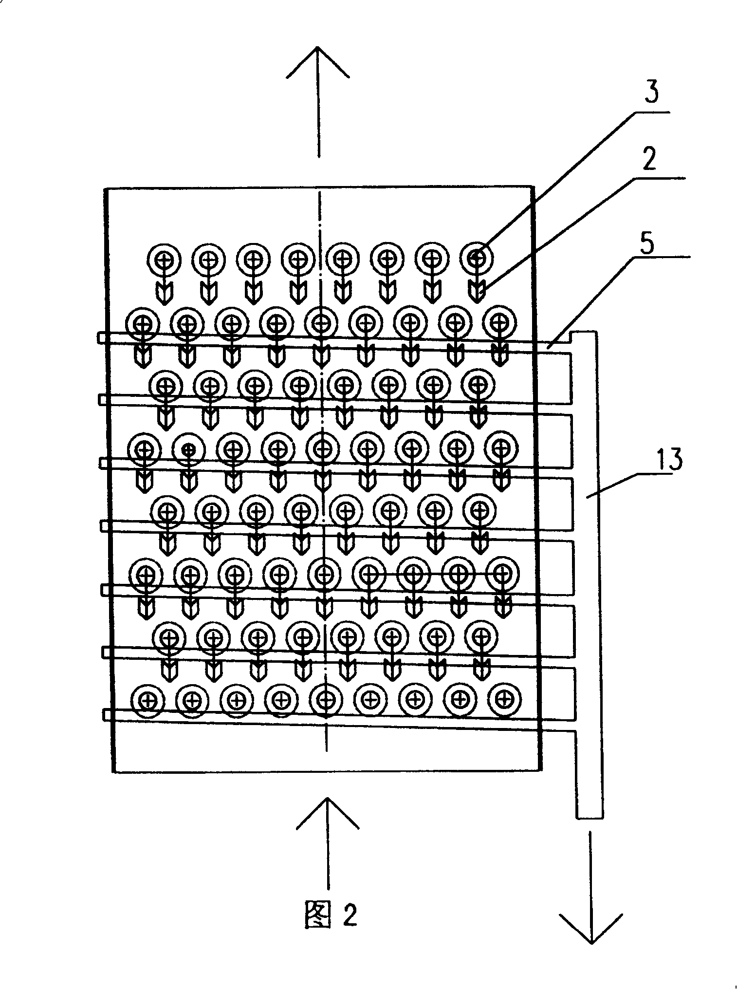
[0014] figure 1 It is a schematic diagram of the structure of the condensate recovery device installed in the condenser. exist figure 1 Among them, the flue gas generated by the combustion of the natural gas boiler enters from the lower flue gas inlet 10 of the condenser, and is discharged from the upper flue gas outlet 1 of the condenser after releasing heat on the surface of each cooling tube 3 inside the condenser. The cooling water enters the first water chamber 4 from the cooling water inlet pipe 6, and flows out through the cooling water outlet pipe 8 of the second water chamber 12, the third water chamber 7, the fourth water chamber 11, and the fifth water chamber 9 in sequence. condenser. The cooling water absorbs the heat in the flue gas and the heat released by the condensation of water vapor through the cooling pipe 3; the flue gas releases heat on the surface of the cooling pipe 3, the water vapor in the flue gas condenses on the surface of the cooling pipe 3, an...


PUM


Abstract

Characters of water recovery arrangement are that there is drainage channel corresponding to each cooling pipe placed in horizontal or declining position inside condenser. The drainage channel is in slant state. Advantages are: reducing condensed water to be vaporized for second time so as to lower resistance of the fume extraction system, make flow of fume more swimmingly and reasonably; eliminating induced draft fan etc. equipment for forcing fume extraction so as to save relevant power and cost; smaller installation space. The invention saves cost of fuel gas, and reduces environmental pollution.

Description

technical field [0001] The invention relates to a boiler condenser. Background technique [0002] At present, natural gas-fired boilers are widely used. After burning natural gas, a large amount of water vapor will be generated. After the complete combustion of natural gas per standard cubic meter, 1.55KG of water vapor will be generated. If these water vapors are condensed into water, 3700KJ of heat will be released, accounting for 100% of natural gas combustion. 10% of the sensible heat part of exothermic heat can be recovered by using the condenser, thus improving the efficiency of the boiler. In practical applications, 1NM3 natural gas combustion produces a theoretical flue gas volume of about 10.3NM3 (about 12.5KG). Taking an excess air coefficient of 1.3 as an example, the flue gas produced is 14NM3 (about 16.6KG). Take the flue gas temperature at 200°C and lower it to 70°C , the physical sensible heat released is about 1600KJ, the water vapor condensation rate is 50%...

Claims


Application Information

Patent Timeline
Patent Type & Authority Patents(China)
IPC IPC(8): F23J15/06
Inventor 王晓伟
Owner 北京东方上达节能设备有限公司
Why Eureka
Try Eureka