Eureka AIR delivers breakthrough ideas for toughest innovation challenges, trusted by R&D personnel around the world.

Tilting-pad bearing built-in motor

A built-in, bearing technology used in electrical components, electromechanical devices, electrical components, etc.

Inactive Publication Date: 2011-06-22
FOSPOVA +1
View PDF0 Cites 0 Cited by
  • Summary
  • Abstract
  • Description
  • Claims
  • Application Information

AI Technical Summary

Problems solved by technology

[0007]However, the working oil volume of the tilting pad bearing is relatively large. If the tilting pad bearing is directly installed on the motor box, it is very easy to enter the fixed position of the motor due to the large amount of oil. The interior of the rotor causes pollution to the stator and rotor of the motor. Therefore, the current domestic motors using tilting pad bearings all adopt a structure in which the bearing and the motor box are separated, which are divided into three parts: the motor stator and rotor module, the left bearing module and the right bearing module. Independent part, the three parts are separated from each other by a certain distance and fixed on the same flat base, the motor rotor is fixed in the middle of the main shaft, and the two ends are respectively supported by the oil film between the left and right bearings and the main shaft
This type of high-speed motor is not compact in structure and takes up a lot of space. When processing, the front bearing seat, rear bearing seat and motor seat must be fixed on the installation plate and processed together to ensure the concentricity of the shaft hole; due to the axial Separate arrangement, large axial size, and large specifications for the machine tool to be processed; at the same time, due to the large axial span, the critical speed of the spindle system is reduced, and this structure is not suitable for application in the field of high-speed motors
The Keqingwa bearing-type high-speed motor with the above-mentioned structure that separates the bearing from the motor stator and rotor has not been widely used in the field of large-scale high-speed rotating machinery due to the above-mentioned defects.

Method used


Image

  • Tilting-pad bearing built-in motor
  • Tilting-pad bearing built-in motor

Examples


Embodiment Construction

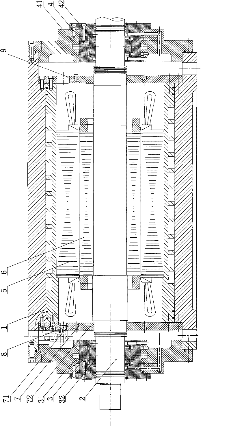
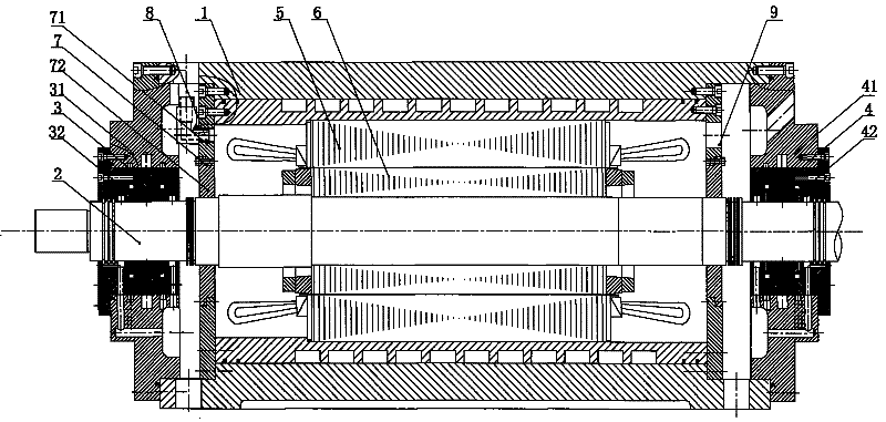
[0026] Such as figure 1As shown, the built-in tilting pad bearing motor of the present invention includes a motor main shaft 2, a front end cover assembly 3, a rear end cover assembly 4, a motor stator 5, a motor rotor 6 and a cuboid motor casing 1, and the motor rotor 6 are set on the motor shaft 2, the motor stator 5 is set in the motor box 1, the motor shaft 2 is placed in the motor stator 5, the two ends of the motor stator 5 are provided with a sealing plate 7, and the sealing plate 7 is set in the Outside the motor shaft 2, it is fixedly connected with the motor case 1 and the motor stator 5. The front end cover assembly 3 includes a front flange 31 and a front tilting pad bearing 32 supported between the front flange 31 and the motor shaft 2. The flange 31 is fixed on the front end of the motor case 1, the rear end cover assembly 4 includes a rear flange 41 and a rear tilting pad bearing 42 supported between the rear flange 41 and the motor main shaft 2, and the rear f...


PUM


Abstract

The invention discloses a tilting-pad bearing built-in motor comprising a motor box, a motor spindle, a front end cover assembly, a rear end cover assembly, a motor stator and a motor rotor, wherein the motor rotor is sleeved on the motor spindle; the motor stator is sleeved in the motor box; the motor spindle is arranged in the motor stator; two ends of the motor stator are both provided with sealing plates sleeved outside the motor spindle and fixedly connected with the motor box and the motor stator; the front end cover assembly comprises a front flange and a front tilting-pad bearing supported between the front flange and the motor spindle, wherein the front flange is fixed at the front end of the motor box; and the rear end cover assembly comprises a rear flange and a rear tilting-pad bearing supported between the rear flange and the motor spindle, wherein the rear flange is fixed at the rear end of the motor box. The tilting-pad bearing built-in motor has the advantages of simple and compact structure, short axial span and high critical speed of shafting.

Description

technical field [0001] The invention relates to the field of mechanical manufacturing, in particular to a high-power high-speed motor supported by a tilting pad bearing. Background technique [0002] Large-scale high-speed and high-power rotating machinery equipment is widely used in national defense, metallurgy, mining, chemical industry and other fields, such as various large fans, turbine compressors, ship power systems and centrifugal compressors. Large-scale high-speed rotating machinery and equipment occupy an extremely important position in my country's national economy. [0003] Traditional high-speed and high-power rotating mechanical equipment mostly uses transmission systems (belt drives, gearbox drives, etc.) to achieve speed increase, and the power source is mostly ordinary motors. Rotating mechanical equipment using this type of transmission mode allows a lower maximum operating speed. Due to the complexity of the transmission system, the vibration and noise a...

Claims


Application Information

Patent Timeline
Patent Type & Authority Patents(China)
IPC IPC(8): H02K5/16
Inventor 熊万里罗春龙蒋旭光侯志泉阳雪兵吕浪
Owner FOSPOVA
Why Eureka
Eureka Blog
Learn More