
Fluorescent temperature sensor probe and manufacturing method thereof

A fluorescent temperature and sensor technology, applied in the field of fluorescent temperature sensor probes, can solve the problems that the sensor cannot measure the ambient temperature of the micro-area, the additional mass of the heat-sensitive area is large, and the measurement accuracy is affected, and achieves small size, simple manufacture and high sensitivity. Effect

Inactive Publication Date: 2010-05-05
NANCHANG HANGKONG UNIVERSITY
View PDF1 Cites 16 Cited by
  • Summary
  • Abstract
  • Description
  • Claims
  • Application Information

AI Technical Summary

Problems solved by technology

When the previous fluorescent temperature sensor uses the same optical waveguide to transmit excitation light and signal light, the signal intensity is low, which affects the measurement accuracy; the additional mass of the thermal sensitive area is large, and the response of the probe to the rapidly changing temperature is hysteresis; The thermal disturbance of the protective cover changes the temperature of the temperature measurement point, so that the sensor cannot measure the ambient temperature of the micro area

Method used


Image

  • Fluorescent temperature sensor probe and manufacturing method thereof
  • Fluorescent temperature sensor probe and manufacturing method thereof

Examples


Embodiment Construction

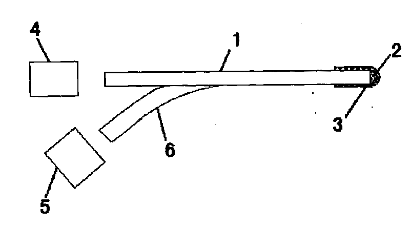
[0012] Such as figure 1 As shown, the temperature sensor is composed of a temperature-sensitive temperature sensor probe, a light source 4, a spectral measurement system 5 and a propagation optical path. The temperature sensor measures the temperature by using the fluorescence characteristics of the temperature-sensitive material that changes with temperature. Optical components such as isolators and polarizing components can also be added to the optical path of the system. Commonly used light sources 4 include mercury lamps and inert gas lamps, such as xenon lamps, deuterium lamps, semiconductor lasers, and tungsten-halogen lamps. According to the luminescent characteristics of fluorescent materials and the absorption characteristics of the excitation light waveguide 1, an excitation light source 4 with a suitable wavelength is selected and selected. A color filter with a suitable wavelength band. The typical propagation path adopts a Y-shaped optical waveguide. The excitatio...


PUM


Abstract

The invention relates to a fluorescent temperature sensor probe which is characterized in that the top of exciting light waveguide is stuck with fluorescent mixture to form the sensor probe which is connected with a reflecting layer. The fluorescent temperature sensor probe has the advantages of tiny body form of the sensor probe, high sensitivity, stable signal, good reliability as well as simple and convenient manufacturing.

Description

technical field [0001] The invention relates to a fluorescent temperature sensor probe, in particular to a fluorescent temperature sensor probe and a manufacturing method thereof. Background technique [0002] The luminescence characteristics of some fluorescent materials have a significant functional relationship with temperature, and the corresponding temperature can be obtained by measuring and calculating the changes in the characteristics of the material's fluorescence intensity, specific intensity, and lifetime. Fluorescent temperature sensors often also have an optical waveguide assembly that propagates the excitation light from the light source and the fluorescent signal from the fluorescent material. Shenzhen University Patent No. 200810065176 is a photonic crystal fiber optic fluorescence temperature sensor and measurement system. The excitation light and signal light can be transmitted through the same optical path or different ones. In patent 200810177040, in a ...

Claims


Application Information

Patent Timeline
IPC IPC(8): G01K11/32
Inventor 张巍巍何兴道高益庆
Owner NANCHANG HANGKONG UNIVERSITY
Learn More