Eureka AIR delivers breakthrough ideas for toughest innovation challenges, trusted by R&D personnel around the world.

Range hood

A range hood and fume collecting hood technology, applied in the field of range hoods, can solve the problems of unsatisfactory grease separation effect, uneven air flow at the fan inlet, increased aerodynamic noise of the fan, etc., and achieves ingenious design, small resistance, and reduced The effect of flow loss

Inactive Publication Date: 2013-08-14
MIDEA GRP CO LTD
View PDF2 Cites 2 Cited by
  • Summary
  • Abstract
  • Description
  • Claims
  • Application Information

AI Technical Summary

Problems solved by technology

For example, the Chinese utility model patent ZL00263535.6 "full-circumferential deflector for range hood" is provided with a deflector at the end side of the air suction port of the casing. Although this structure improves the smoke exhaust efficiency to a certain extent, it does not The following problems are ignored: first, the deflector is located above the fan inlet, and the aerodynamic circumvention caused by the deflector causes the airflow at the fan inlet to be very uneven, which directly increases the aerodynamic noise of the fan; second, the flue gas After bypassing the deflector, it directly enters the fan without any filter device. Although the deflector plays a certain role in condensation separation, the oil separation effect of the whole machine is not satisfactory; third, the structure of the oil circuit is complicated
Although the small-aperture filter can play the role of rectifying and reducing noise and improving the separation of grease, it will also cause a sharp drop in the air volume of the hood due to too much resistance, and the small-aperture filter is easy to block, requiring frequent cleaning, and it is inconvenient to disassemble and wash.

Method used


Image

  • Range hood
  • Range hood
  • Range hood

Examples


Embodiment

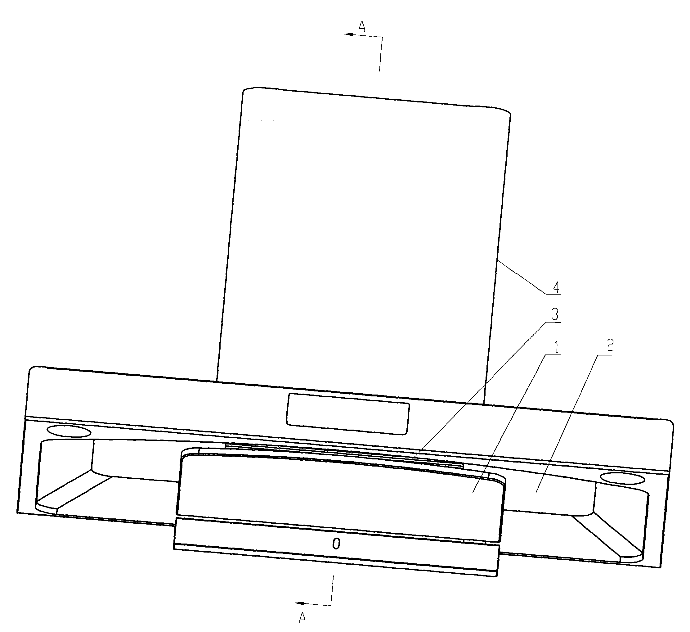
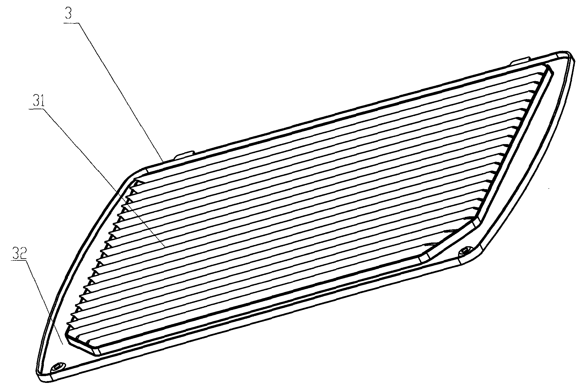
[0032] The structure diagram of the present invention is as figure 1 , 2 , 3, and 4, the range hood of the present invention includes a smoke guide plate 1, a smoke collecting hood 2, a rectifying net 3 and a box body 4, wherein the smoke collecting cover 2 is provided with an air inlet 21, and the smoke guide plate 1 The air inlet 21 is set right, and a predetermined distance is kept from the fume collecting hood 2. The fan system 5 is arranged in the box 4 above the fume collecting hood 2, and a rectifying net is provided at the air inlet 21 of the fume collecting hood 2. 3. The rectifying net 3 is fixed on the air inlet 21 of the smoke collecting hood 2, wherein the rectifying net 3 includes a row of straight and long blades 31, and the straight and long blades 31 are arranged along the front and rear direction of the hood.

[0033] The cross-section of the above-mentioned straight long blades 31 is a plane in-line airfoil cascade, and the passage of the plane in-line airf...


PUM


Abstract

The invention relates to a range hood which comprises a smoke deflector (1), a smoke collecting hood (2), a rectifying screen (3) and a box body (4), wherein the smoke collecting hood (2) is provided with an air inlet (21); the smoke deflector (1) is arranged just facing the air inlet (21), and a preset distance is maintained between the smoke deflector and the smoke collecting hood (2); the box body (4) arranged above the smoke collecting hood (2) is internally provided with a fan system (5); and the air inlet (21) of the smoke collecting hood (2) is provided with the rectifying screen (3) which is fixed on the air inlet (21) of the smoke collecting hood (2). The range hood is characterized in that the rectifying screen (3) comprises a row of long strip blades (31) which are arranged along the front and back direction of the range hood, and the cross sections of the long strip blades (31) are plane orthostichous wing-type blade lattices; a plane orthostichous wing-type blade lattice channel is in a contractive state to form an accelerating blade channel; and the direction of an outlet (6) of the blade channel is bias towards one side of an air inlet (51) of the fan system (5). The range hood has the advantages of low noise, high smoke exhaust efficiency, no blocking and no-clean.

Description

technical field [0001] The invention relates to a range hood, which belongs to the modification technology of the range hood. Background technique [0002] Noise, air volume, adsorption force and grease separation are the four important performance indicators of range hoods. In order to improve the overall performance of the range hood, people have done a lot of practical research. Although some performance indicators have achieved certain results, they often lose sight of the other and fail to achieve the improvement of the overall performance. For example, the Chinese utility model patent ZL00263535.6 "full-circumferential deflector for range hood" is provided with a deflector at the end side of the air suction port of the casing. Although this structure improves the smoke exhaust efficiency to a certain extent, it does not The following problems are ignored: first, the deflector is located above the fan inlet, and the aerodynamic circumvention caused by the deflector cau...

Claims


Application Information

Patent Timeline
Patent Type & Authority Patents(China)
IPC IPC(8): F24C15/20
Inventor 粱之博李星季俊生
Owner MIDEA GRP CO LTD
Why Eureka
Eureka Blog
Learn More