
Automotive hybrid eddy current retarder

A hybrid, retarder technology, applied in asynchronous induction clutches/brakes, etc., can solve the problems of inability to provide braking torque, long working response time, small braking torque, etc., to improve work performance, reduce manufacturing and The effect of running costs and reducing energy consumption

Inactive Publication Date: 2010-04-28
JIANGSU UNIV
View PDF0 Cites 3 Cited by
  • Summary
  • Abstract
  • Description
  • Claims
  • Application Information

AI Technical Summary

Problems solved by technology

At the same time, it also has the following disadvantages: because the gas in the cylinder is required to push the permanent magnet back and forth, not only the structure is more complicated, but also the working response time is longer
The magnetic field generated by the permanent magnet is weak, so the generated braking torque is small. Since the generation of the magnetic field cannot be controlled by changing the current size and the number of magnetic pole groups like the electromagnet, it cannot be provided according to the actual situation of the vehicle. different braking torques

Method used


Image

  • Automotive hybrid eddy current retarder
  • Automotive hybrid eddy current retarder
  • Automotive hybrid eddy current retarder

Examples


Embodiment Construction

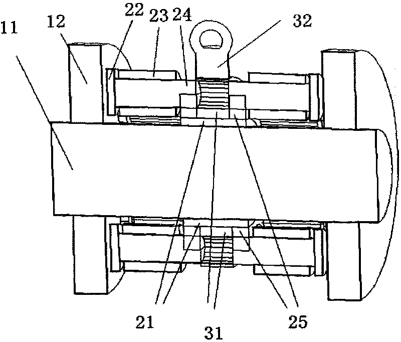
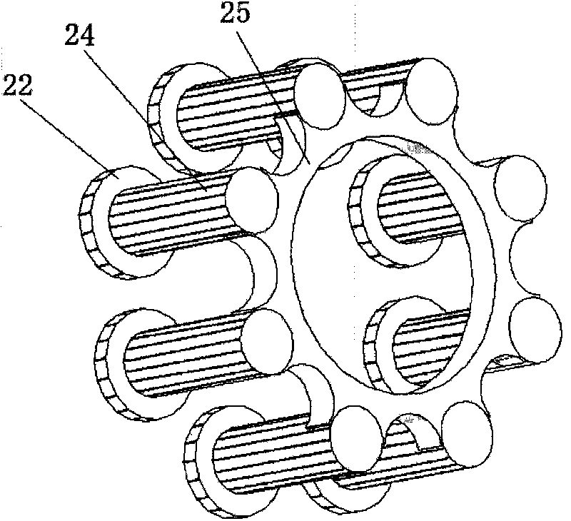
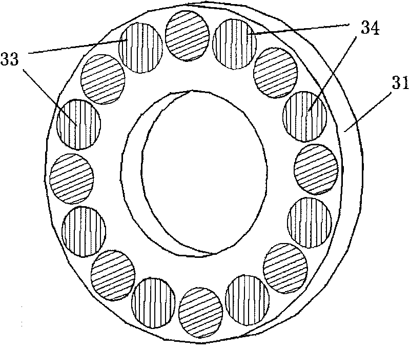
[0016] Such as figure 1 , 2 As shown, the two ends of the rotating shaft 11 are fitted with a rotor disk 12 , and the middle of the rotating shaft 11 is fitted with an annular fixed disk 31 . Between the fixed disk 31 on the left side and the rotor disk 12, and between the fixed disk 31 on the right side and the rotor disk 12, a set of stator tooth sets with brackets 25 are arranged symmetrically, and the brackets 25 are sleeved on the rotating shaft 11. That is, the fixed disk 31 is arranged between the two brackets 25 , and the two stator tooth groups are symmetrically arranged on both sides of the fixed disk 31 . Wherein, each group of stator teeth has 8 stator teeth 24 , and each stator tooth 24 is wound with a winding 23 . One end of each stator tooth 24 is connected to a corresponding magnetic yoke 22 , and the other end is fixed on a bracket 25 . There is a gap in the axial direction between the yoke 22 and the rotor disk 12 .

[0017] The bearing 21 is fixedly slee...


PUM


Abstract

The invention discloses an automotive hybrid eddy current retarder. A rotor disk is fixedly sleeved on each end of a rotating shaft; a fixed disk is fixedly sleeved on the middle of the rotating shaft; two stator tooth groups with brackets are arranged between the fixed disk and the rotor disk symmetrically and respectively; the brackets are sleeved on the rotating shaft; each stator tooth group has 8 stator teeth; one end of each stator tooth is connected with a magnet yoke and the other end thereof is fixed on the bracket; an axial gap is preserved between the magnet yoke and the rotor disk; the windings corresponding to the two symmetrical stator tooth groups have the same winding direction; the windings on the two adjacent stator teeth in each stator tooth group have opposite winding directions; the fixed disk is uniformly distributed with 16 holes along a circumferential direction; 8 cylindrical permanent magnets and 8 cylindrical iron cores are embedded into the 16 holes alternately; and the cylindrical permanent magnets are magnetized axially and the magnetizing directions of the adjacent permanent magnets are opposite. Two working states, namely a electric eddy current retarder state or a permanent magnet retarder state, are realized, energy consumption is reduced, volume and temperature rise are reduced and operation faults are reduced.

Description

technical field [0001] The invention relates to a retarder for automobile auxiliary braking, in particular to an electric eddy current retarder and a permanent magnet eddy current retarder. Background technique [0002] At present, in the technical field of eddy current retarders, electric eddy current retarders and permanent magnet eddy current retarders have been widely used. These two types of eddy current retarders use the electromagnetic field to transmit the braking torque, which can bear most of the braking load of the car, reduce the mechanical friction braking load, have better stability in the braking direction, and reduce the braking squeal of the brake. Reduces brake noise, reduces brake dust pollution, effectively reduces brake temperature, prolongs the service life of brake linings and tires, shortens maintenance and maintenance time, effectively reduces traffic accidents caused by brake failure, and improves driving comfort and safety sex. [0003] The perma...

Claims


Application Information

Patent Timeline
Patent Type & Authority Applications(China)
IPC IPC(8): H02K49/04
Inventor 何仁费德成
Owner JIANGSU UNIV
Learn More