
Device for measuring large-scaled bulb tubular hydraulic generator rotor

A water turbine generator, light bulb through-flow technology, applied in the direction of mechanical diameter measurement, etc., can solve the problems of high labor intensity, accuracy error, time-consuming efficiency, etc. Effect

Inactive Publication Date: 2012-07-04
TIANJIN TIRNFR HEAVY HYDROELECTRIC FRCILITY CO LTD
View PDF0 Cites 0 Cited by
  • Summary
  • Abstract
  • Description
  • Claims
  • Application Information

AI Technical Summary

Problems solved by technology

[0003] At present, the generator rotor measuring device is to make two sleeves on the top of the main shaft in advance, one is a stop sleeve and the other is a rotating sleeve, the bracket of the measuring frame is welded on the outer diameter of the rotating sleeve, and the measuring rod It can only be measured by extending to the measured part of the rotor, and the top of the main shaft is 4000-6000 mm high according to the measured part of the rotor (the capacity of the generator is different, and the height of the main shaft is different), and the measuring rod also needs 4000-6000 mm. Because the length of the measuring rod will inevitably cause errors in its accuracy, and the staff who measure the height must use tools to climb to the top of the main shaft to push the bracket to measure the circumference of the rotor, so the labor intensity of the workers is high, the accuracy of the measurement is poor, and the cost of materials is high. , time-consuming and inefficient

Method used


Image

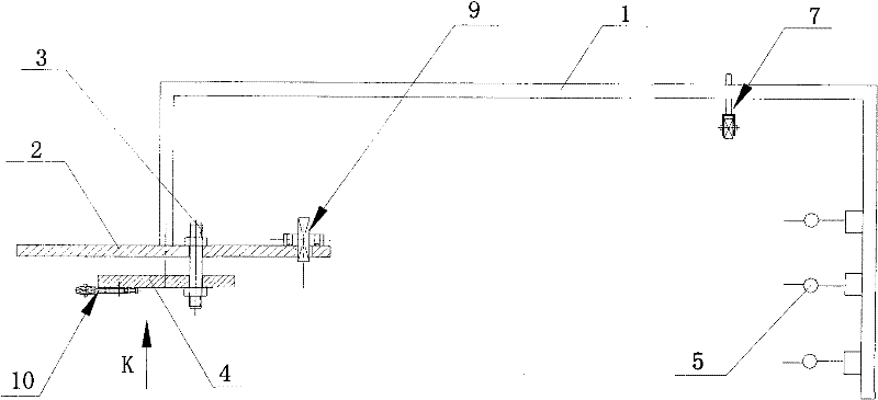
  • Device for measuring large-scaled bulb tubular hydraulic generator rotor
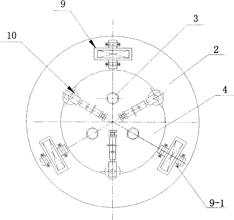
  • Device for measuring large-scaled bulb tubular hydraulic generator rotor
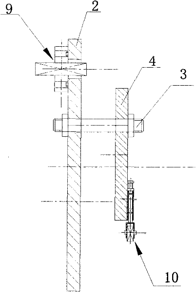
  • Device for measuring large-scaled bulb tubular hydraulic generator rotor

Examples


Embodiment

[0023] Example: see Figure 1 to Figure 3 , a rotor measuring device for a large bulb tubular hydroelectric generator, the patented measuring device includes a П-shaped rotor measuring frame 1, an upper turntable 2 connected to the left side of the rotor measuring frame 1, and the upper turntable 2 passes through fasteners The connecting bolt 3 connects the lower turntable 4 which is located on the lower side of the upper turntable 2 and is installed parallel to the upper turntable 2. On the inner wall on the right side of the rotor measuring frame 1, several dial gauges 5 for measuring magnetic poles are installed, and the hands of the dial gauge 5 extend to the magnetic poles. 6; the inside of the top of the rotor measuring frame 1 is provided with a bearing device 7, the bearing device 7 fits with the hub 8-1 of the rotor bracket 8, please refer to Figure 4 and Figure 5 , the bearing device 7 includes a bearing seat 7-1 bent into a П shape, a screw rod 7-2 is installed o...


PUM


Abstract

The invention relates to a device for measuring a large-scaled bulb tubular hydraulic generator rotor. The device is characterized in that: the device comprises a rotor measuring frame, an upper rotary disk connected to the left side of the rotor measuring frame, a lower rotary disk connected with the upper rotary disk and a dial indicator which is arranged the inner wall on the right side of therotor measuring frame and of which a hand is extended to the external diameter of a magnetic pole, wherein the inner side on the top part of the rotor measuring frame is provided with a bearing device stuck to a hub of the rotor frame; the upper rotary disk is evenly provided with a plurality of bearing devices along a circumferential direction, and each bearing device is stuck to the upper flange surface of the rotor frame; and the lower end surface of the lower rotary disk is evenly provided with a plurality of horizontal bearing devices along the circumferential direction, and each bearingdevice is stuck to the inner porous surface of the rotor frame. The device can be produced by waste scraps in power stations or assembling fields, so that the cost is saved, the measurement is quick and accurate, the time and labor are saved, and the production efficiency is improved. The device has the advantages of quick measurement, easy operation, accurate data, time-saving and labor-saving measurement and the like.

Description

technical field [0001] The invention belongs to the technical field of hydroelectric power generation, in particular to a measuring device for the rotor of a large bulb tubular hydroelectric generator. Background technique [0002] The rotor of the bulb tubular hydroelectric generator is an important part of the hydroelectric generator. Its structure is to hang several magnetic poles evenly on the outer diameter of the rotor bracket to form a rotor. It is a high-speed rotating Components, the outer diameter of the usual hydraulic generator rotor is up to 10,000 mm, and the gap between the inner diameter of the stator and the outer diameter of the rotor that matches the rotor is only 5 to 9 mm, and the gap between the stator and the rotor is the hydraulic generator. If the gap is not uniform, it will cause changes in the magnetic field and cause vibration and noise of the generator, which will cause accidents. Therefore, the size of the outer diameter of each rotor must meet ...

Claims


Application Information

Patent Timeline
Patent Type & Authority Patents(China)
IPC IPC(8): G01B5/08
Inventor 邵春华郭洁
Owner TIANJIN TIRNFR HEAVY HYDROELECTRIC FRCILITY CO LTD
Learn More