Clamping device of optical detector

An optical detector and clamping device technology, used in measuring devices, scientific instruments, material analysis by optical means, etc., can solve the problem that the clamping device cannot contact the PCB board, cannot contact the PCB board, and the central deformation of the PCB board and other problems, to achieve the effect of not easy to deform, improve positioning accuracy, and avoid skew

Inactive Publication Date: 2010-04-21
SUZHOU MINGFU AUTOMATIC SCI & TECH
View PDF0 Cites 7 Cited by
  • Summary
  • Abstract
  • Description
  • Claims
  • Application Information

AI Technical Summary

Problems solved by technology

[0004] The clamping device of the optical detector of the present invention solves the problem that the PCB board is deformed toward the center and the clamping device cannot touch the PCB board during the clamping process from the macroscopic structural design, and provides a reasonable design, not easy to deform, and a clamping position Clamping device for robust optical detector
Through such a structural design, the clamping device presses the edge of the PCB board from top to bottom during the clamping process, so from the macro design, it solves the problem that the ordinary clamping device exerts force on the center of the PCB board during the clamping process, which is easy The problem of causing the deformation of the PCB board to the center, and canceling the clamping plate originally located in the movement groove of the PCB board, solved the problem that the clamping device cannot touch the PCB board

Method used


Image

  • Clamping device of optical detector
  • Clamping device of optical detector
  • Clamping device of optical detector

Examples


Embodiment Construction

[0014] The present invention will be described in detail below in conjunction with the accompanying drawings.

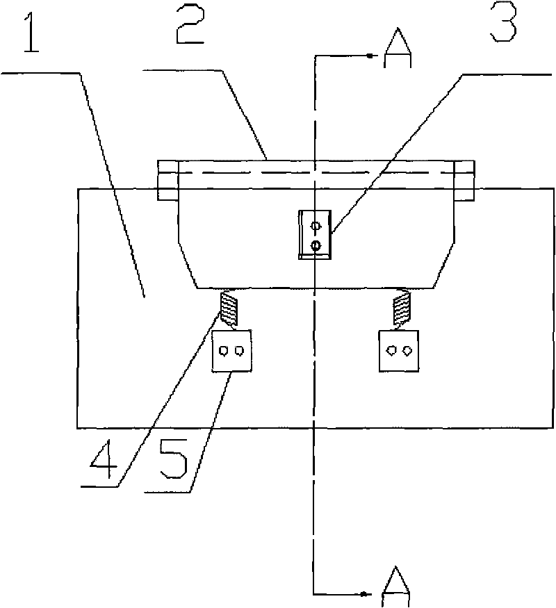
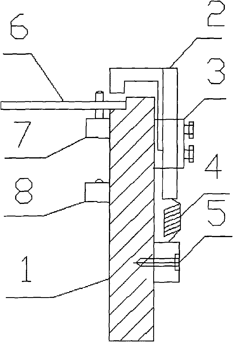
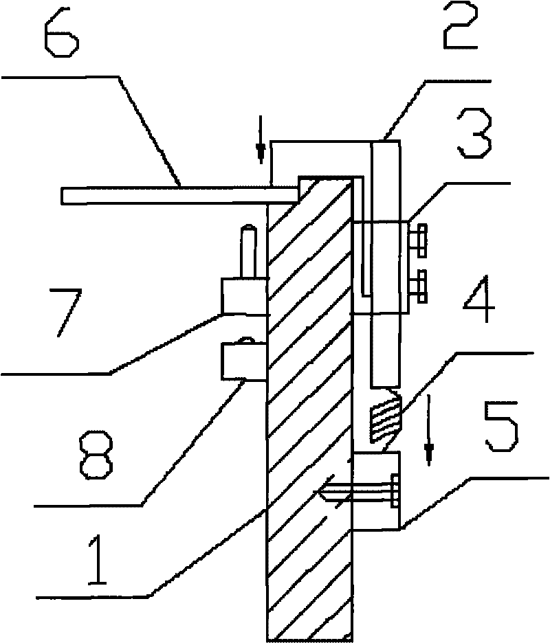
[0015] Such as figure 1 As shown, the clamping device of the optical detector of the present invention is mainly a kind of clamping device of the optical detector, comprising a clamp body 1, a clamp plate 2 positioned on the clamp body 1, a cylinder 3 on the clamp plate 2 and a clamp body located on the clamp body 1. The baffle plate 7 and the inductor 8 on the concrete 1, the top of the clamp body 1 is stepped, and the clamp plate 2 is an inverted "L" shape that matches the top of the clamp body 1, and is in contact with the top and one side of the clamp body 1. touch.

[0016] The bottom of the clamp plate 2 is connected with the spring seat 5 on the clamp body 1 through the spring 4 . When the air cylinder is inflated to drive the fixture plate to move downward to compress the workpiece, the stretching performance of the spring plays a buffer role in the process...


PUM


Abstract

The invention discloses a clamping device of an optical detector, which comprises a clamp body (1), a clamp plate (2) positioned on the clamp body (1), a cylinder (3) on the clamp plate (2), and a baffle plate (7) and an inductor (8) which are positioned on the clamp body (1). The top of the clamp body (1) is step-shaped, the clamp plate (2) has a reverse L-shape inosculated with the top of the clamp body (1) and is contacted with the top and one side of the clamp body (1). The clamping device of the optical detector has the advantages of automatically positioning and clamping workpieces; and meanwhile, a spring and a spring seat are increased so as to play a role in buffering when the clamp plate presses the workpieces, a PCB is not damaged, and the design of the step-shaped clamp body can prevent the PCB from deflecting so as to improve the positioning precision.

Description

technical field [0001] The invention relates to a clamping device, in particular to a clamping device for an optical detector. Background technique [0002] The optical detector is a kind of equipment used to detect solder joints on the PCB board. At present, the clamping device of the optical detector on the market mainly adopts a rigid clamping device. When the PCB board is sent to the inspection station, the sensor of the optical detector The signal is received, and the baffle at the front end of the detection station is controlled by the cylinder to rise, and the baffle is used to prevent the PCB from moving back and forth. At the same time, the cylinder controls the clamping plates on both sides of the PCB to shrink inward and exert pressure on the PCB. So that the PCB board is fixed, and then further testing is carried out. [0003] However, since this type of clamping device is a rigid clamping plate with force exerted on the left and right sides, it is easy to cause...

Claims


Application Information

Patent Timeline
Patent Type & Authority Applications(China)
IPC IPC(8): G01N21/01G01N21/84
Inventor 庄春明
Owner SUZHOU MINGFU AUTOMATIC SCI & TECH
Why Eureka
Try Eureka