
Vertebral arch pedicle extension device

A technique for extending the device and pedicle, which is applied in the field of lumbar spinal stenosis surgery, can solve the problems of high operation difficulty, large surgical trauma, and long operation time, and achieves the effects of strong operability, less trauma, and short operation time.

Inactive Publication Date: 2010-04-21
杨惠林 +3
View PDF0 Cites 6 Cited by
  • Summary
  • Abstract
  • Description
  • Claims
  • Application Information

AI Technical Summary

Problems solved by technology

[0005] However, in the above method, the appendages, ligaments and other tissues and structures on the posterior side of the spine are removed during the operation, which not only damages the spine and destroys its stability, but also easily damages the nerves. disease, so the operation trauma is large and the patient suffers a lot; at the same time, the operation is difficult and complicated, the operation time is long, and the cost is high

Method used


Image

  • Vertebral arch pedicle extension device
  • Vertebral arch pedicle extension device
  • Vertebral arch pedicle extension device

Examples


Embodiment 1

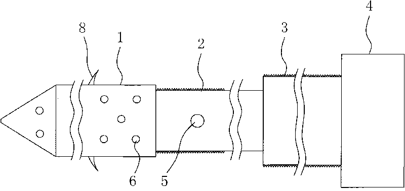
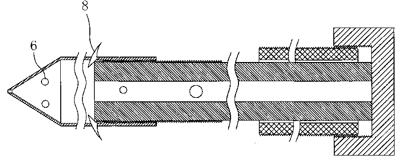
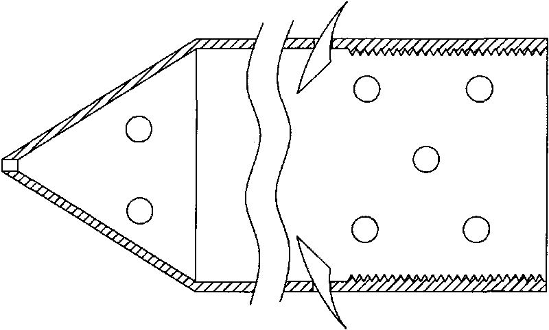
[0042] See attached Figure 1-8 As shown, a pedicle extension device includes a front nail 1, a mandrel 2, a rear nail 3 and a fixator 4, the mandrel 2 is a hollow structure, the middle part of which is provided with a communicating through hole 5, and its front end is connected to the The front nail 1 is threaded, the rear end of which is sleeved with the rear nail 3, and the core rod is slidingly connected with the rear nail; the fixer is fixedly connected to the rear end of the rear nail, and relatively fixes the core rod and the rear nail. The fixer 4 is a rear nut, and the outer surface of the rear nail is provided with an external thread matched with the rear nut, and one end of the rear nut is closed, so that the mandrel will touch the back nail and the rear nut when they are threaded. In the rear nut, the core rod and the rear nail are relatively fixed.

[0043] The front nail is provided with an inner cavity matched with the mandrel, and the outer surface of the fron...

Embodiment 2

[0049] See attached Figures 9 to 16 As shown, a pedicle extension device includes a front nail 1, a mandrel 2, a rear nail 3 and a fixator 4, the mandrel 2 is a hollow structure, the middle part of which is provided with a communicating through hole 5, and its front end is connected to the The front nail 1 is threaded, the rear end of which is sleeved with the rear nail 3, and the core rod is slidingly connected with the rear nail; the fixer is fixedly connected to the rear end of the rear nail, and relatively fixes the core rod and the rear nail. The fixer 4 is a back nut, the outer surface of the back nail is provided with external threads that cooperate with the back nut, the middle part of the back nut is provided with a through hole, and the through hole is provided with an internal thread. The rear end of the core rod is provided with an external thread matched therewith, so that the core rod and the rear nail are relatively fixed when the back nail and the back nut are...


PUM


Abstract

The invention discloses a vertebral arch pedicle extension device, which comprises a front nail, a core bar, a rear nail and a fixer. The core bar has a hollow structure, wherein the middle part of the core bar is provided with a through hole, the front end of the core bar is connected with the front nail by screw thread, the rear end of the core bar is sleeved with the rear nail, and the core bar is glidingly connected with the rear nail; the fixer is fixedly connected at the rear end of the rear nail and enables the core bar and the rear nail to be fixed oppositely. The vertebral arch pedicle extension device can separate a centrum from a vertebral arch pedicle and extend the distance therebetween, finally achieve the aims of expanding a vertebral canal and an intervertebral foramina and reducing pressure, can be applied to surgical operation on stenosis of the lumbar spine and has good application prospect.

Description

technical field [0001] The invention belongs to the field of lumbar spinal canal stenosis surgery, and in particular relates to a pedicle extension device. Background technique [0002] With the aggravation of population aging and the bad working and living habits of modern people, the incidence of lumbar spinal stenosis is increasing. Lumbar spinal stenosis refers to a series of clinical symptoms caused by bone hyperplasia or fibrous tissue hyperplasia caused by various reasons, hypertrophy leading to shortening of the sagittal diameter of the spinal canal or nerve root canal, stimulation and compression of nerve roots or cauda equina; Lumbar spinal stenosis can be uniplane (two adjacent vertebral bodies, intervertebral discs, facet joints, and supporting ligaments) or multiplane (involving two or more spaces). Its typical clinical manifestations are: bilateral neurogenic claudication, intermittent thigh or calf radiating pain, aggravated by prolonged standing, activity or...

Claims


Application Information

Patent Timeline
IPC IPC(8): A61B17/70
Inventor 杨惠林唐天驷刘家勇刘凌
Owner 杨惠林
Learn More