
Method for producing printed board combining rigidness and flexibleness

A production method and a combination of rigid and flexible technology, which is applied in the fields of printed circuit manufacturing, printed circuit, printed circuit assembly of electrical components, etc., can solve the problems of difficult lamination of covering film, expensive PTFE material, difficult selection, etc., and achieves a solution The difficulty of choosing gaskets, avoiding production quality problems, and improving the effect of production quality

Active Publication Date: 2010-04-14
SHENZHEN KING BROTHER ELECTRONICS TECH
View PDF0 Cites 43 Cited by
  • Summary
  • Abstract
  • Description
  • Claims
  • Application Information

AI Technical Summary

Problems solved by technology

[0006] 1. It is difficult to choose the thickness of the PTFE gasket used as the conformal material. The thickness of the gasket will affect the lamination quality of the hard board area, and the thin gasket will affect the lamination quality of the covering film. In addition, PTFE material is relatively expensive
[0007] 2. The PTFE gasket used after lamination cannot protect the flexible board that needs to be exposed, because in the subsequent wet process, various chemicals will seep into the flexible board area through the gasket and the edge of the rigid board groove, resulting in liquid attack Flexible board, so in general, the gasket should be removed after lamination, and the flexible board should be protected by red tape or peelable blue glue
[0008] 3. It is difficult to press the cover film by one-time lamination, especially for the finer lines, the cover film cannot be well filled between the lines, and the cover film will cause blistering in the subsequent mounting process

Method used


Image

  • Method for producing printed board combining rigidness and flexibleness
  • Method for producing printed board combining rigidness and flexibleness
  • Method for producing printed board combining rigidness and flexibleness

Examples


Embodiment Construction

[0026] The purpose of the present invention is to provide a method for opening windows of rigid-flexible printed boards, using existing equipment, and by improving the production process, it overcomes the difficulties in the previous production process and more effectively produces products that meet the quality requirements. Rigid-flex printed boards.

[0027] Before laminating the rigid part and the flexible part of the rigid-flex printed circuit, the preprocessing of the rigid part and the flexible part is carried out separately.

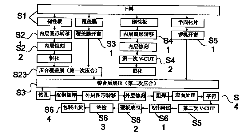
[0028] refer to figure 2 , figure 2 It is a flow chart of the production method of a rigid-flexible printed board of the present invention; first, according to the circuit production process of the prior art, S1: open the flexible board, rigid board, cover film, and low resin fluidity prepreg; S21 : Then transfer the inner layer circuit pattern to each layer of the flexible board, S22: Etch the circuit on the flexible board; S31: Then open th...


PUM


Abstract

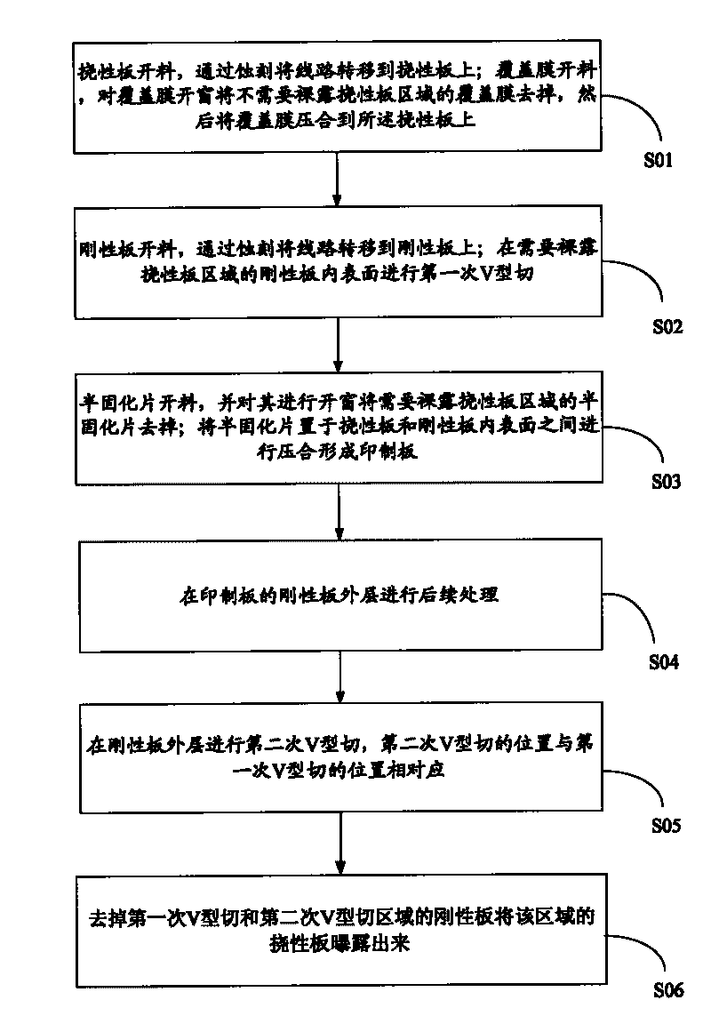
The invention provides a method for producing a printed board combining rigidness and flexibleness, comprising the following steps: cutting a flexible board and transferring an inner-layer circuit pattern onto the flexible board; cutting a covering film, implement windowing on the covering film, and pressing the covering film onto the flexible board; cutting a rigid board and transferring the inner-layer circuit pattern onto the rigid board; implementing a primary V type cutting at an outline position needing to baring the flexible board area; cutting a prepreg, implementing windowing on the prepreg and removing the prepreg needing to baring the flexible board area; placing the prepreg between the inner surfaces of the flexible board and the rigid board for implementing pressing so as to form a printed board; implementing subsequent processing at the outer layer of the rigid board of the printed board; implementing a secondary V type cutting at the outer layer of the rigid board, and leading the position of the secondary V type cutting to correspond to the position of the primary V type cutting; removing the rigid board of the primary V type cutting and the secondary V type cutting area; and exposing the flexible board of the area. The method improves the production quality of the printed board combining rigidness and flexibleness.

Description

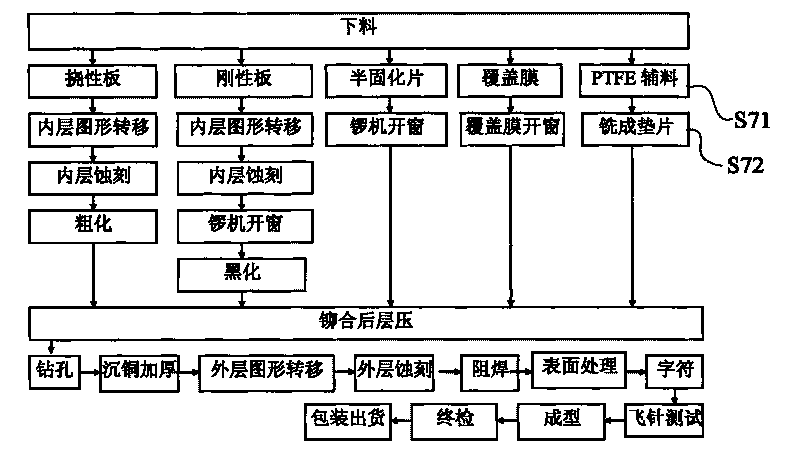
technical field [0001] The invention relates to the technical field of production of printed boards, in particular to a method for producing rigid-flexible printed boards. Background technique [0002] Rigid-flex printed board refers to a printed circuit board that contains one or more rigid areas and one or more flexible areas on a printed board; this printed circuit board is actually the first rigid printed circuit board The circuit board part and the flexible printed circuit board part are made separately, and then they are made together when they are laminated, formed and hot-pressed. Rigid-flex printed boards have been widely used in consumer electronic products such as mobile phones and digital cameras. They can reduce the assembly size and weight of electronic products, avoid wiring errors, realize three-dimensional assembly under different assembly conditions, and have Light, thin, short and small. [0003] refer to figure 1 The process flow chart of the early sta...

Claims


Application Information

Patent Timeline
Patent Type & Authority Applications(China)
IPC IPC(8): H05K3/00H05K3/36
Inventor 陈裕韬刘敏严俊锋朱占植范思维
Owner SHENZHEN KING BROTHER ELECTRONICS TECH
Learn More