
Electric-control wide-angle light scanning device and array thereof

A light scanning device, wide-angle technology, applied in the direction of optics, optical components, instruments, etc., to achieve the effect of high steering rate

Inactive Publication Date: 2010-04-14
NANJING UNIV OF POSTS & TELECOMM
View PDF0 Cites 11 Cited by
  • Summary
  • Abstract
  • Description
  • Claims
  • Application Information

AI Technical Summary

Problems solved by technology

[0004] Technical problem: The purpose of this invention is to propose an electronically controlled wide-angle optical scanning device and its array device structure, so as to solve the problem of electronically controlled tuning of wide-beam scanning devices

Method used


Image

  • Electric-control wide-angle light scanning device and array thereof
  • Electric-control wide-angle light scanning device and array thereof
  • Electric-control wide-angle light scanning device and array thereof

Examples


specific Embodiment 1

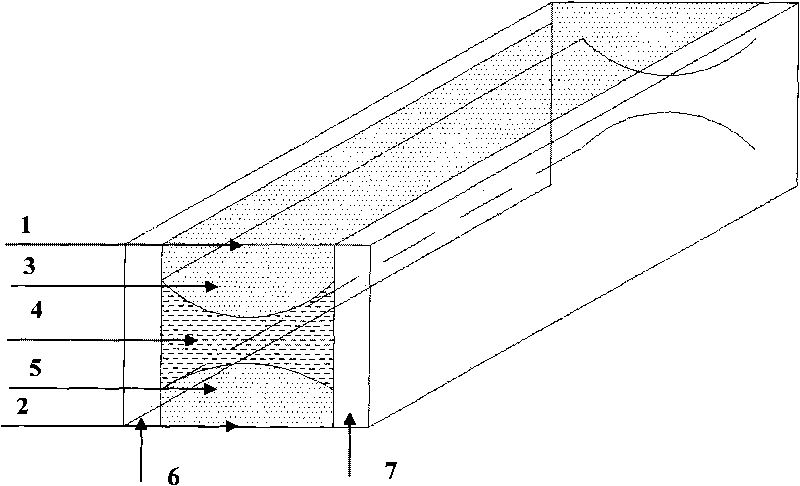
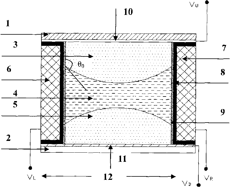
[0041] like figure 1 , 2 As shown, the conductive materials 6 and 7 on the left and right sides are metal materials with good electrical conductivity, and a 3-micron-thick parylene is formed as the insulating layer 8 on the surface of the metal material by vacuum coating. The hydrophobic layer 9 is realized by dipping the hydrophobic agent FOTs. Conductive Fluids 3 and 5 use a saline solution which may have freezing problems when used at low temperatures. High concentration salt solutions can be used to lower the freezing point. In order to maintain the low density and refractive index of the brine, a low atomic weight salt is used: lithium chloride. Lithium chloride at a concentration of 20% results in a freezing point below -40°C, a density ρ of 1.12kg / m3, and a refractive index of 1.38. Insulating fluid 4 uses a mixed phenylmethylsiloxane, which has a high refractive index and good electrowetting properties. Dissolve a few percent carbon tetrabromide (ρ=2.96kg / m 3 ) ...

specific Embodiment 2

[0044] like figure 1 , 2 As shown, the conductive materials 6 and 7 on the left and right sides are doped conductive material Si, and a layer of 500nm SiO is oxidized on the surface of Si. 2 as an insulating layer 8. The transparent substrate still uses a high-performance cover glass sputtered ITO film layer. The hydrophobic layer 9 is realized by dipping the hydrophobic agent FOTs. Use a saline solution. Hydrophobic layer 9 adopts polytetrafluoroethylene polymer material (English abbreviation is PTFE, trade name Teflon Teflon@AF) coating to achieve. The insulating fluid is bromododecane (density 1.0399, refractive index 1.4583), and the conductive fluids 3 and 5 are saline solutions configured to have the same density to remove the influence of gravity. The voltage controls the shape of the interface between the insulating fluid and the conductive fluid to adjust the shape and position of the liquid prism, thereby realizing the electronically controlled wide beam pola...

specific Embodiment 3

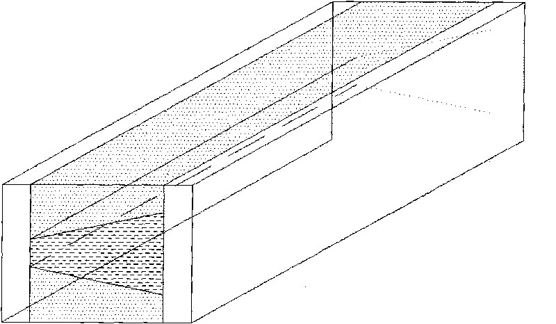
[0045] Other manufacturing process is the same as embodiment 1 and 2. The electronically controlled wide-angle optical scanning device of embodiment 1 or 2 is made into an electronically controlled optical scanning array device (transverse linear, vertical linear and planar) by the bonding method, or an array device is fabricated on a whole piece of base material. On the basis of Embodiment 1 or 2, the long channel-shaped liquid tank is designed as a square liquid tank, and then the front and rear walls are made of conductive materials, and an insulating layer is arranged between the front and rear walls and the left and right walls.


PUM

PropertyMeasurementUnit
Freezing pointaaaaaaaaaa
Densityaaaaaaaaaa

Abstract

The invention relates to an electric-control wide-angle light scanning device and an array thereof. The device is a container for a fluid prism which can contain a conductive fluid, an insulation fluid and another conductive fluid, such as a fluid bath. The upper end and the lower end of the fluid bath are respectively provided with a transparent upper cover plate (1) and a transparent lower cover plate (2), and a fluid prism cavity used for storing fluid prism materials is formed by the space between the transparent upper cover plate (1) and the transparent lower cover plate (2). Three indissoluble fluids, namely a first conductive fluid (3), an insulation fluid (4) and a second conductive fluid (5) are respectively arranged in the fluid bath from top to bottom. The three fluids form fluid prism media and respectively have different refractive indexes. A left wall (6) and a right wall (7) of the fluid bath are made of conductive materials and are respectively used as a left electrode and a right electrode, and an upper electrode and a lower electrode are respectively arranged in an upper transparent conductive layer (10) on the upper cover plate and a lower transparent conductive layer (11) on the lower cover plate. Under the control of a voltage-controlled system (11), the device forms an edge-adjustable fluid prism system.

Description

technical field [0001] The invention relates to an electronically controlled wide-angle optical scanning device, its array structure and its working principle, and belongs to the technical fields of optical communication, photoelectric sensing and image processing. Background technique [0002] High-speed and precise reconfiguration of light beams is a major factor for free-space optical communication and laser detection (lidar). To continue to improve system-level performance for these applications, there has been a need for connectors that overcome bulk, loss, low speed, and flexibility with mechanical beam steering like biaxial mirrors. These needs have inspired many new inventions in order to find new ways to achieve beam steering. Some approaches are available today: acousto-optic and electro-optic devices, prisms and lenses, optical arrays based on dynamic liquid crystal gratings, and liquid crystal polarization rotators containing multilayer interfaces. Significant ...

Claims


Application Information

Patent Timeline
IPC IPC(8): G02B26/02
Inventor 陈陶梁忠诚
Owner NANJING UNIV OF POSTS & TELECOMM
Learn More