
Linked voltage regulation non-excitation tap switch

A tap changer and excitation technology, applied in transformers, variable transformers, contact electrical connections, etc., can solve the problems of inconvenient and cumbersome use of switches, and a large number of coil taps, etc., and achieve high working reliability, simple and compact structure, The effect of the small size of the switch

Inactive Publication Date: 2010-04-07
WUHAN TAIPU TRANSFORMER CHANGER
View PDF0 Cites 2 Cited by
  • Summary
  • Abstract
  • Description
  • Claims
  • Application Information

AI Technical Summary

Problems solved by technology

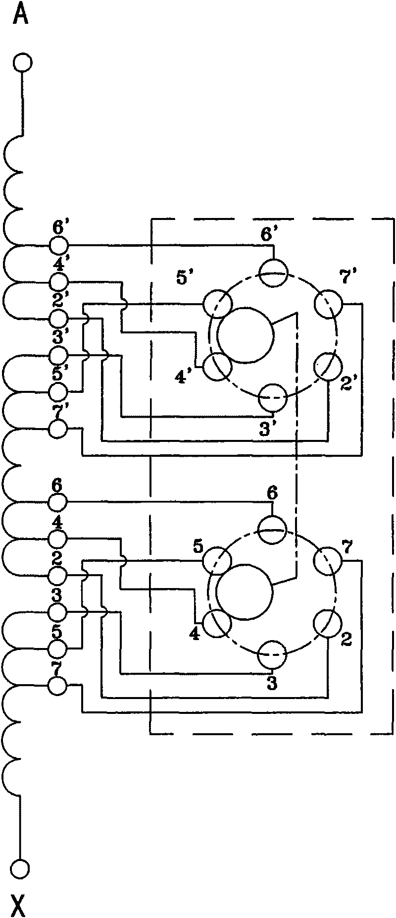
The upper and lower parts of the one-phase coil are tapped to the switch at the same time, and each part has a total of 6 taps. The moving contacts of the two-layer switch of one phase rotate synchronously to realize 5-level voltage regulation, and the two layers are mutually insulated; if it is three The phase has 6 layers of contact groups, and each phase is also insulated from each other. This kind of switch is relatively simple and convenient, but when there are many gears, the number of coil taps is large, and the transformer structure is also relatively complicated.
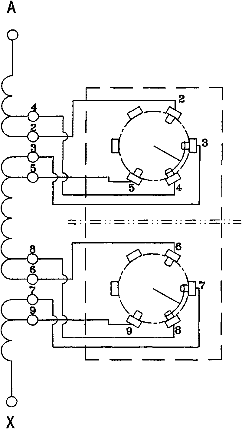
However, if the transformer coil is designed as figure 2 As shown, the coil structure is simple, each section only draws 4 heads, and the upper and lower sections draw a total of 8 heads. The combination of the upper and lower sections can still achieve five-speed voltage regulation. At this time, two independent ordinary switches are generally used to realize it separately. One is adjusted to the upper section, and the other is adjusted to the lower section. The differential combination achieves a five-level voltage regulation effect, and the insulation level between adjacent static contacts is reduced. However, after increasing the number of switches, the transformer structure is complicated, the cost is increased, and the switch is used. It is inconvenient and reduces reliability. It is very cumbersome to implement the two switches on the external mechanism through linkage

Method used


Image

  • Linked voltage regulation non-excitation tap switch
  • Linked voltage regulation non-excitation tap switch
  • Linked voltage regulation non-excitation tap switch

Examples


Embodiment Construction

[0032] Embodiments of the present invention will be further described below in conjunction with the accompanying drawings.

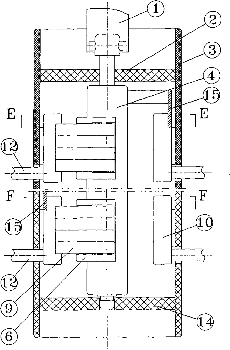
[0033] The first embodiment of the present invention is Figure 3-6 As shown, it is a single-phase drum-shaped linkage voltage-regulating off-excitation tap-changer, including a cylindrical insulator 3 and upper and lower supports 2, 14. A rotating shaft 4 is installed in the middle of the upper and lower supports, and the middle part of the rotating shaft is an insulator. , the upper end of the rotating shaft is connected to the operating mechanism 1, and two layers of static contacts 10 correspondingly distributed along the circumferential direction are installed on the inner side of the insulating cylinder. The two layers of static contacts are insulated from each other, and the static contacts are cylindrical static contacts. The rear end of the static contact is a lead joint 12, which is used to connect with the tap; corresponding to each layer of s...


PUM


Abstract

The invention relates to a linked voltage regulation non-excitation tap switch for a transformer, which comprises an insulator, an upper support, a lower support and a rotating shaft; and each phase corresponding to the switch is provided with two layers of static contacts and moving contacts bridged with two adjacent static contacts. The tap switch is characterized in that: one layer of the two layers of static contacts of each phase is provided with static contacts of an upper or a lower voltage regulation tap of a linked voltage regulation coil, the two adjacent static contacts form a tap position, the tap positions are distributed along a circumferential direction in reduced progressively sequence from large to small, and another minimum tap position is repeatedly arranged after one minimum tap position; the other layer is provided with static contacts of a lower or an upper voltage regulation tap of the linked voltage regulation coil, the tap positions are distributed along the circumferential direction in reduced progressively sequence from large to small, and another maximum tap position is repeatedly arranged before one maximum tap position; and the maximum tap position in one layer of the two layers of static contacts set in each phase corresponds to the foremost tap position of the maximum tap position arranged in the other layer. The tap switch is simple and compact in structure and reasonable in setting, achieves multi-tap voltage regulation by using less voltage regulation coil taps, can complete operation at one time, and has high reliability and convenient use.

Description

technical field [0001] The invention relates to a linkage voltage regulation non-excitation tap changer for a transformer. Background technique [0002] The voltage regulation principle of the existing transformer voltage regulation coil is as follows: figure 1 As shown, the dotted box is the switch part, a total of five levels of voltage regulation. The upper and lower parts of the one-phase coil are tapped to the switch at the same time, and each part has a total of 6 taps. The moving contacts of the two-layer switch of one phase rotate synchronously to realize 5-level voltage regulation, and the two layers are mutually insulated; if it is three The phase has 6 layers of contact groups, and each phase is also insulated from each other. This kind of switch is relatively simple and convenient, but when there are many gears, the number of coil taps is large, and the transformer structure is also relatively complicated. However, if the transformer coil is designed as figur...

Claims


Application Information

Patent Timeline
IPC IPC(8): H01F29/04H01H1/56H01H1/58
Inventor 刘刚
Owner WUHAN TAIPU TRANSFORMER CHANGER
Learn More