
Wave crest seeking method and wave crest seeking system

A wave peak and system state technology, applied in the field of wave peak search, can solve the problems of low accuracy, multiple instruction cycles, and limitation of the speed of the fiber grating data demodulation system, achieving fast speed, high precision, saving storage space and waveform analysis the effect of time

Inactive Publication Date: 2012-07-04
WUHAN UNIV OF TECH
View PDF0 Cites 0 Cited by
  • Summary
  • Abstract
  • Description
  • Claims
  • Application Information

AI Technical Summary

Problems solved by technology

[0005] However, using the polynomial-Gaussian formula fitting method instruction or the Gaussian formula fitting method instruction to find the peak needs to have enough memory to store the data of one cycle of collection, and the instruction needs to consume a lot of instruction cycles, thus not only affecting the wave peak The speed of the search, but also limits the speed of the FBG data demodulation system
However, the use of successive comparison instructions to find the peaks is achieved by successive comparisons, so the accuracy is not high and the anti-interference ability is weak.
Based on the above discussion, the above-mentioned peak-finding methods using the three instructions are not suitable for fiber grating data demodulation systems that require high system speed and accuracy.

Method used


Image

  • Wave crest seeking method and wave crest seeking system
  • Wave crest seeking method and wave crest seeking system
  • Wave crest seeking method and wave crest seeking system

Examples


Embodiment Construction

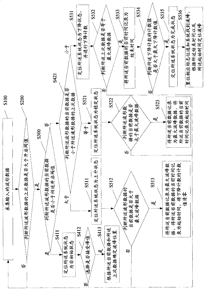
[0025] Embodiments of the present invention will now be described with reference to the drawings, in which like reference numerals represent like elements. As mentioned above, the peak-finding method and the peak-finding system of the present invention do not require a large amount of storage space and many instruction cycles, and the peak-finding accuracy is high. It will be elaborated below.

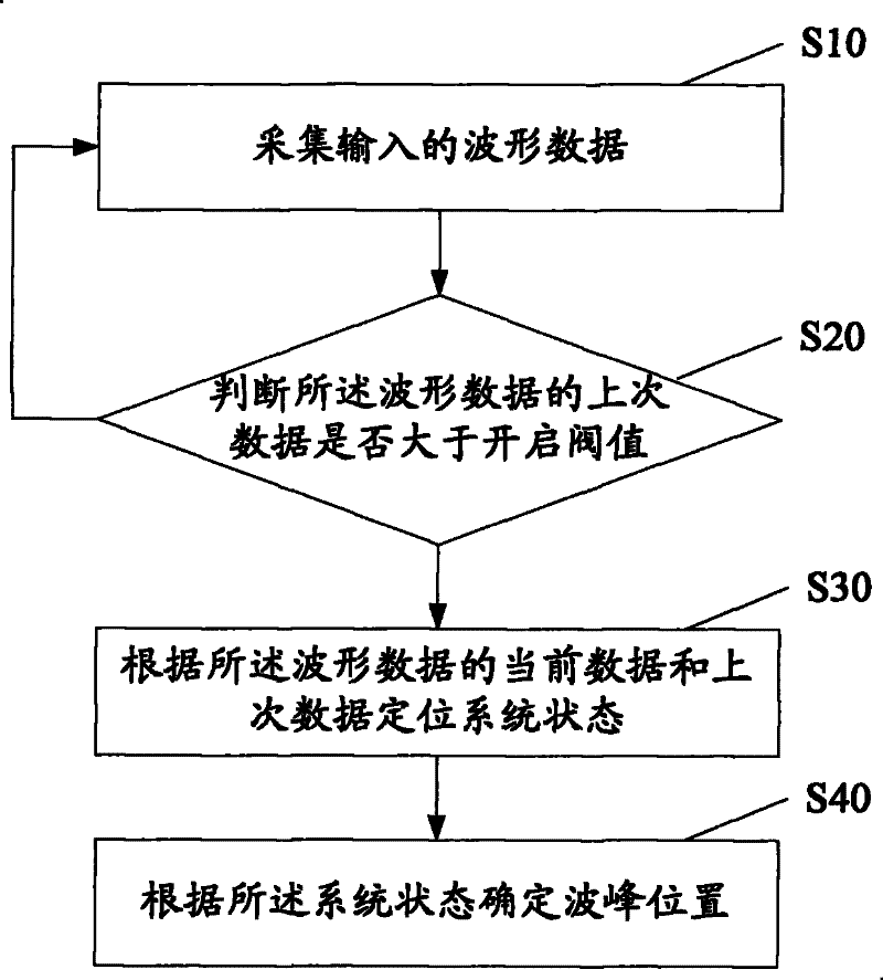
[0026] figure 1 It is a flow chart of the peak finding method of the present invention. Such as figure 1 Shown, described peak finding method comprises the steps:

[0027] Step S10: collecting input waveform data;

[0028] Step S20: Judging whether the last data of the waveform data is greater than the opening threshold (the opening threshold can be dynamically set according to the actual environment. The judging step is to filter out system interference caused by power supply, wiring, etc.) , when the last data of the waveform data is less than the opening threshold (the last dat...


PUM


Abstract

The invention discloses a wave crest seeking method. The wave crest seeking method comprises the following steps: acquiring input waveform data; positioning the state of a system according to the current data and the last data of the waveform data; and determining the position of a wave crest according to the state of the system. The wave crest seeking method of the invention does not need a large amount of storage space and numerous instruction cycles, and has high crest seeking precision. The invention discloses a wave crest seeking system at the same time.

Description

technical field [0001] The invention relates to a fiber grating data transmission system, in particular to a method and a system for finding wave peaks in the fiber grating data transmission system. Background technique [0002] With the introduction of fiber gratings, various complex all-fiber communication and sensor networks have spread throughout the entire communication field. Fiber Bragg gratings are being used more and more because of their high transmission rate and low attenuation. The manufacturing process of the existing fiber grating is as follows: through a certain process, the incident photon from the outside interacts with the doped particles in the fiber core, resulting in periodic or non-periodic permanent changes in the refractive index of the fiber core along the axial direction. A spatial phase grating is formed inside. [0003] Fiber grating data transmission system includes data modulation system and data demodulation system. The data modulation syst...

Claims


Application Information

Patent Timeline
Patent Type & Authority Patents(China)
IPC IPC(8): G02F2/00H04B10/12H04B10/25
Inventor 周祖德程松林李方敏王欢
Owner WUHAN UNIV OF TECH
Learn More