Switch device

A switching device and switching element technology, applied in electronic switches, electrical components, pulse technology and other directions, can solve the problems of mechanical device functional interference, long push-in stroke, poor operation convenience, etc., to reduce the required space and components. Quantity, space saving effect

Inactive Publication Date: 2010-03-31
HUF HULSBECK & FURST GMBH & CO KG
View PDF1 Cites 12 Cited by
  • Summary
  • Abstract
  • Description
  • Claims
  • Application Information

AI Technical Summary

Problems solved by technology

Disadvantages of this type of ignition switch have been found to be that such an ignition switch has poor operating convenience due to the long push-in stroke, and that the function of the complex mechanism is easily disturbed by external environmental influences

Method used


Image

  • Switch device
  • Switch device
  • Switch device

Examples


Embodiment Construction

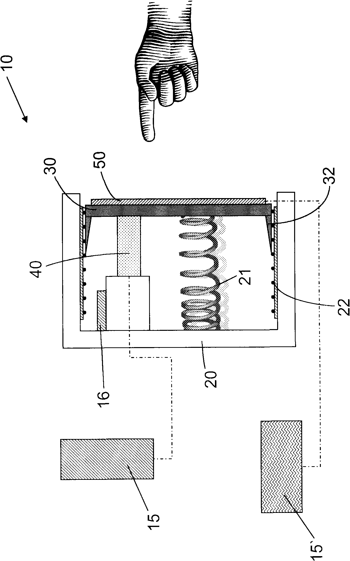
[0027] figure 1 A first advantageous embodiment of a switching device 10 is shown, which is used to switch on or off an electrical consumer, in particular an engine or the like in a vehicle. The switching device 10 has a housing 20 , an actuating element 30 , a switching element 40 and a display 50 . The display 50 is arranged on the actuating element 30 , and the switching element 40 can be activated via the actuating element 30 . At least one switching signal 17 for the control unit 15, 15' can be generated by means of the switching element 40. It is provided according to the invention that the switching element 40 is a piezoelectric switch. Such piezo switches are arranged in such a way that when the actuating element 30 is pushed 31 into the housing 20 , a switching signal 17 is generated.

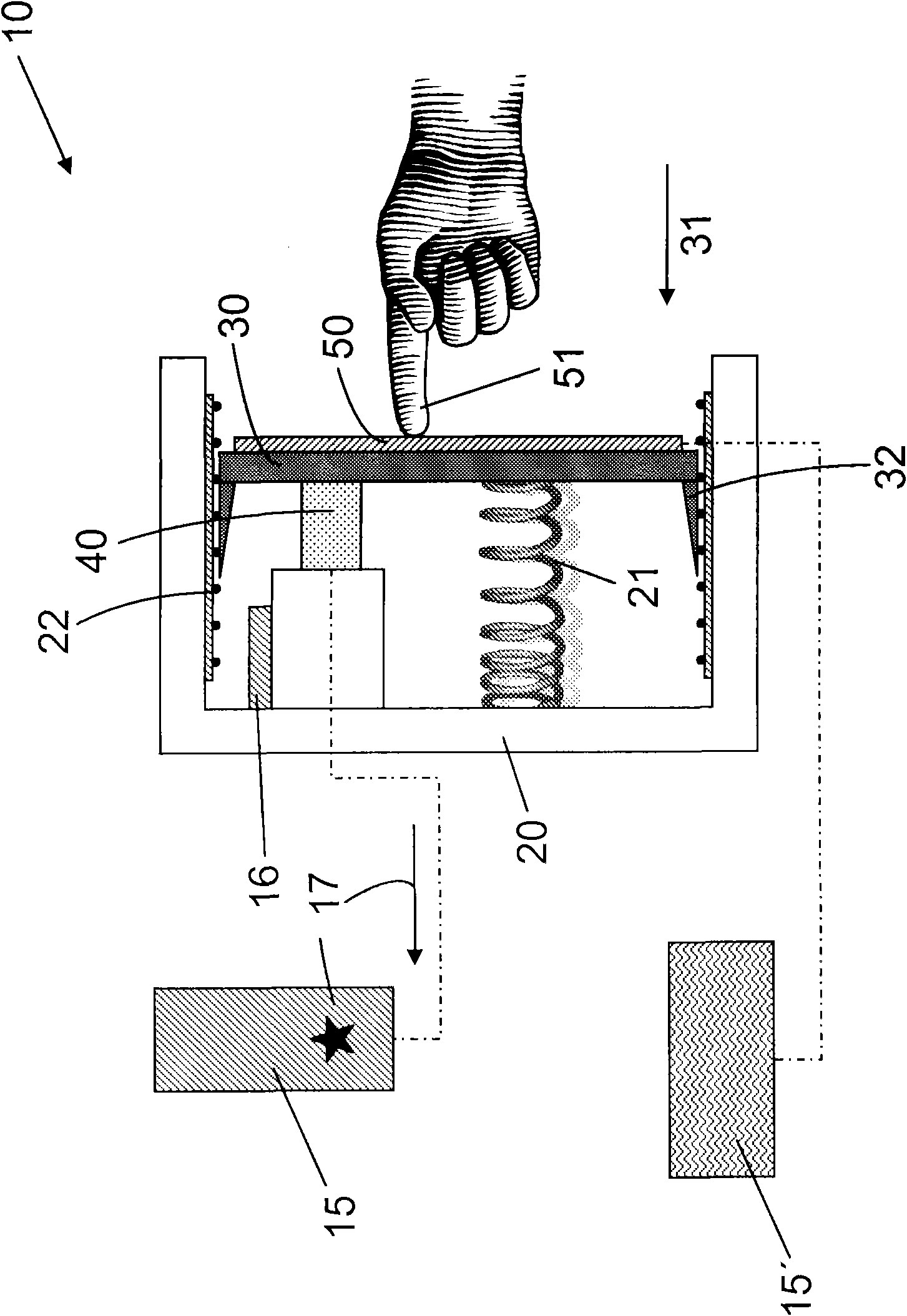
[0028] figure 2 Pushing 31 of the actuating element 30 into the housing 20 is shown. It can be seen that the actuating element 30 is displaced relative to the housing 20 and exer...


PUM


Abstract

The invention relates to a switch device (10), for switching a user on and off, in particular, a motor or similar in a vehicle, comprising a housing (20), an operating element (30), a switch element (40) and a display (50), wherein the display (50) is arranged on the operating element (30), the switch element (40) may be activated by the operating element (30) and at least one switch signal (117)for a control unit (15,15') may be generated by means of the switch element (40). According to the invention, the switch element (40) is a piezo switch and the piezo switch is arranged such as to generate the switch signal (17) on pushing (31) the operating element (30) into the housing (20).

Description

technical field [0001] The invention relates to a switching device for switching on or off an electric consumer, in particular an engine or the like in a vehicle, the switching device has a housing, an operating element, a switching element and a display, wherein the display is arranged on the operating element Above, the switching element can be activated by the actuating element, by means of which at least one switching signal for the control unit can be generated. Background technique [0002] An ignition switch is described in DE 101 64 558 A1, which is used to switch the vehicle engine on or off. The ignition switch is arranged near the steering column and has a movable body arranged in the housing. Furthermore, a switch body is integrated in the ignition switch, which holds the movable body movable and serves to detect a displacement of the movable body. In addition, an indicator device for displaying the state of the vehicle is located near the movable body. In thi...

Claims


Application Information

Patent Timeline
Patent Type & Authority Applications(China)
IPC IPC(8): H03K17/96
CPCH03K17/964H03K17/965
Inventor 斯特凡·默尼希克里斯托夫·布劳纳斯特凡·特龙贝伦斯安德烈亚斯·法尔肯贝格英戈·波兰哈拉尔德·迪克尔斯
Owner HUF HULSBECK & FURST GMBH & CO KG
Why Eureka
Try Eureka