Eureka AIR delivers breakthrough ideas for toughest innovation challenges, trusted by R&D personnel around the world.

Terminal for power supply connector, power supply connector and power supply connector assembly

A power connector and terminal technology, which is applied in the direction of connection, contact parts, electrical components, etc., can solve the problems of narrow insertion opening, collapse, terminal deformation, etc., and achieve the effect of reducing damage, reducing possibility, and reducing deformation

Active Publication Date: 2010-03-31
ALLTOP ELECTRONICS SU ZHOU +1
View PDF1 Cites 0 Cited by
  • Summary
  • Abstract
  • Description
  • Claims
  • Application Information

AI Technical Summary

Problems solved by technology

[0003] Since the insertion opening of the female terminal is usually very narrow, not only is it not conducive to terminal lapping, but also during lapping, the contact arm of the male terminal in the free state is easily deformed due to improper force, which increases the defective rate
In addition, the use environment of the power connector is not always good, so that foreign matter is easy to invade the terminal, for example, the mating space of the female terminal or the male terminal, which may cause deformation and collapse of the terminal

Method used


Image

  • Terminal for power supply connector, power supply connector and power supply connector assembly
  • Terminal for power supply connector, power supply connector and power supply connector assembly
  • Terminal for power supply connector, power supply connector and power supply connector assembly

Examples


Embodiment Construction

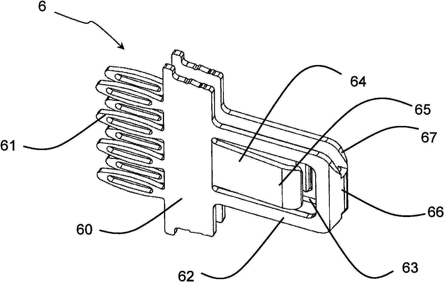
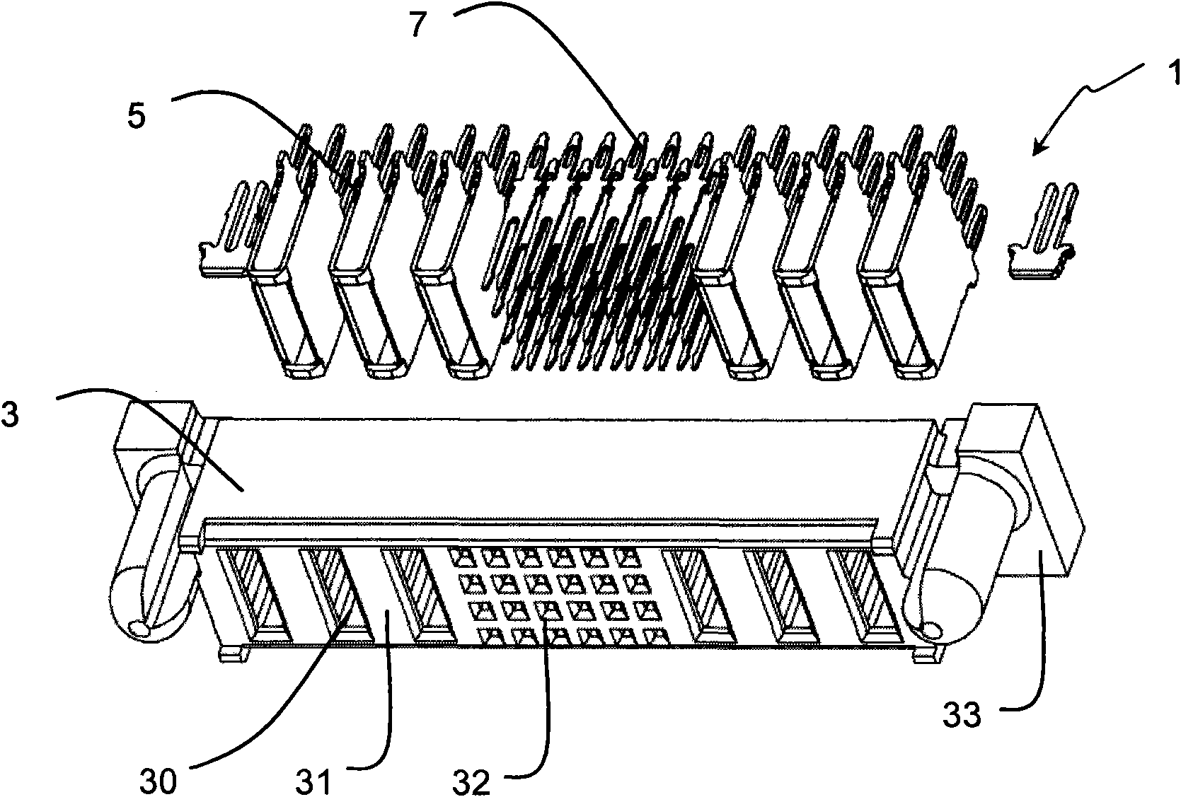
[0035] figure 1 An exploded perspective view of the plug connector 2 according to a preferred embodiment of the present invention is shown. Such as figure 1 As shown, the plug connector 2 includes a plug insulating body 4 , a plurality of male terminals 6 and a plurality of male signal terminals 8 fixed in the plug insulating body 4 for power transmission.

[0036] In this embodiment, the plug insulating body 4 has a substantially rectangular parallelepiped outer contour. The insulating plug body 4 has a plurality of terminal fixing grooves 40 for receiving and fixing corresponding parts of the corresponding terminals 6 , 8 . The plug insulating body 4 forms a groove 41 at its front end. Contact portions (described in detail below) of the male terminal 6 and the male signal terminal 8 are exposed in the groove 41 . When mating with the receptacle connector 4 , the front surface 42 of the plug insulator body 4 is in contact with the corresponding surface of the receptacle i...


PUM


Abstract

The invention relates to a terminal for a power supply connector. The terminal comprises a pair of walls which are arranged opposite to each other and spaced at a preset distance. The terminal also comprises a terminal protecting structure for bridging the front ends of a pair of walls according to the suggestion of the invention. The invention also provides a power supply connector containing theterminal and a power supply connector assembly.

Description

technical field [0001] The present invention relates to a terminal for a power connector, a power connector and a power connector assembly, in particular to a power connector terminal and a power connector for power transmission between circuit boards or between backplane connection systems And a power connector assembly including a receptacle connector and a plug connector. Background technique [0002] Power connectors are known in the art. For example, US Pat. No. 6,319,075 discloses a power connector assembly for transferring power between two circuit boards or between backplane connection systems. Wherein, the plug connector and the socket connector respectively include an insulating body and a plurality of power terminals accommodated and fixed in the insulating body. The male terminal and the female terminal respectively accommodated in the plug connector and the receptacle connector respectively have mounting feet for being mounted on corresponding circuit boards a...

Claims


Application Information

Patent Timeline
IPC IPC(8): H01R13/04H01R13/10H01R24/06H01R24/10H01R24/00
Inventor 郑义宏刘阔正
Owner ALLTOP ELECTRONICS SU ZHOU
Why Eureka
Eureka Blog
Learn More