
Installation switch device with protective device

A switchgear and cover technology, which is applied in the field of installation switchgear that can be covered by a cover, can solve the problems of complex structure of the cover, and achieve the effect of simple structure

Inactive Publication Date: 2014-08-20
ABB (SCHWEIZ) AG
View PDF5 Cites 0 Cited by
  • Summary
  • Abstract
  • Description
  • Claims
  • Application Information

AI Technical Summary

Problems solved by technology

The structure of this cover is complicated, and the installation of the switchgear requires a special modification, namely the said recess, in order to enable the cover to be snapped into place with it

Method used


Image

  • Installation switch device with protective device
  • Installation switch device with protective device
  • Installation switch device with protective device

Examples


Embodiment Construction

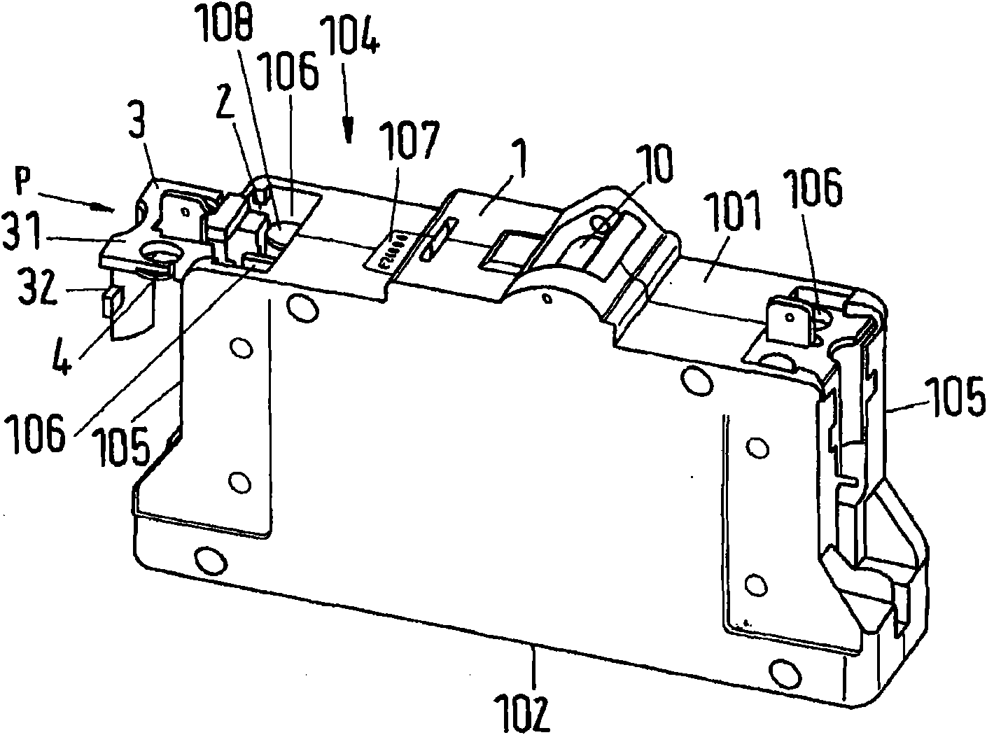
[0026] As an example of the installation switchgear of the present invention, figure 1 The main line protection switch 1 is shown. The principle of the function and internal structure of the main line protection switch is known. The main line protection switch 1 has a housing 101 of insulating material. The housing of insulating material comprises a fixing side 102 , with which the housing of insulating material can be fixed on a fixing surface such as a wall, or it can also be fixed on an installation distribution box or a support rail. On the front side 104 opposite to the fixed side 102, an operating mechanism 10 protrudes, here a switch knob, with which the installation switchgear can be switched on and off. In the vicinity of the actuating mechanism 10 , a nameplate 107 is arranged on the front, on which the serial number of the device is visible. The front side 104 and the fastening side 102 are connected by two wide sides and two narrow sides 105 .

[0027] On the ...


PUM


Abstract

The device (1) has an insulating material housing (101) fixable at a wall. The housing exhibits an actuating body (10) at a front side (104). A covering hood is detachably coupled at the device. The hood covers the device for preventing unauthorized access to connection terminals. A coupling element (3) i.e. sealing cap, is detachably connected with the housing. The coupling element has a resting element for fixing the covering hood at the coupling element, and a punched hole for preventing unauthorized removing of the covering hood, which comprises of a ventilation slot.

Description

technical field [0001] The invention relates to an installation switchgear that can be covered by a cover, comprising a housing of insulating material, which can be fastened to a wall by fixing sides, the installation switchgear having at least one actuating mechanism on the front side, And the terminals of the installation switchgear can be connected with electric leads, the housing of insulating material includes a cover releasably coupled with the installation switchgear, the cover is removed from all The sides cover the mounting switchgear, while leaving free space for fixed sides and operating mechanisms. Background technique [0002] Such installed switchgear of the type described ( ) is, for example, a safety main switch, abbreviated SHU or main circuit breaker, which is usually installed between a load transfer point (Stromübergabe punkt) and an electricity meter in domestic electricity installations. [0003] In particular, the main line protection switch is not ...

Claims


Application Information

Patent Timeline
Patent Type & Authority Patents(China)
IPC IPC(8): H01H9/02H01H9/20
CPCH01H71/08H01H9/0264H01H71/0264
Inventor R·克劳斯
Owner ABB (SCHWEIZ) AG
Learn More