


Quick Research
Generate reliable direction feasibility study reports for your R&D in just a few steps.

Technical Q&A
Discover and master advanced knowledge NOW. Basics, ideas, possibilities, all at once.

Find Solutions
As an expert in R&D theories, this can generate solutions to your technical problems instantly.

Evaluate Feasibility
Analyze your overall solution with one click, know your potential R&D risks in advance.

Monitor Landscape
Get weekly tech updates, stay abreast of the latest tech innovations and key insights.
Nail scissors
A technology of nail scissors and elastic boards, applied in manicure or pedicure tools, clothing, applications, etc., can solve the problems of increased transportation costs, multiple materials for nail clippers, etc., and achieve the effect of saving material procurement costs
- Summary
- Abstract
- Description
- Claims
- Application Information
AI Technical Summary
Problems solved by technology
Method used
Image

Examples
Embodiment Construction
[0022] The present invention will be further described below in conjunction with drawings and embodiments.
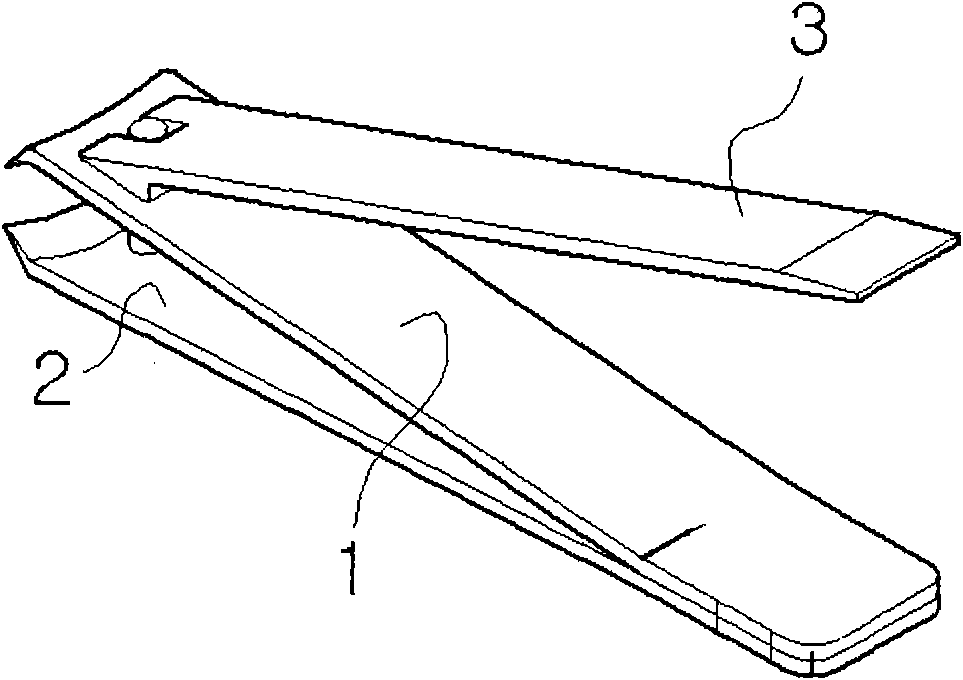
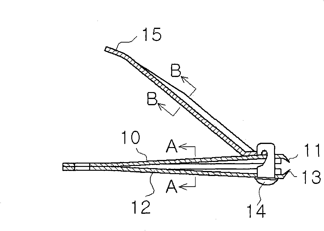
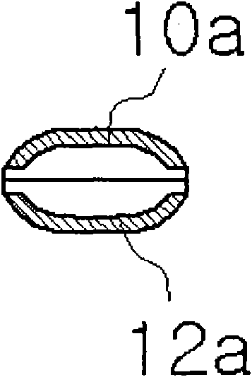
[0023] figure 2 , image 3 and Figure 4 It is a sectional view of an embodiment of the present invention. The front end of the nail scissors of the present invention has an upper elastic plate 10 with a cutting edge 11 and a rear end of a lower elastic plate 12 with a cutting edge 13 combined by welding, and a support rod 14 runs through the front to combine the front end of the pressing plate 15, It is characterized in that: the thickness of the upper and lower elastic plates 10, 12 is thinner than the existing thickness, and the cross section is processed into image 3 and Figure 8 As shown in the arc-shaped end faces 10a, 12a, the thickness of the above-mentioned pressing plate 15 is also relatively thin and its cross section becomes Figure 4 and Figure 9 The arcuate end face 15a is shown.
[0024] Figure 5 , Image 6 and Figure 7 is a cross-sectiona...
PUM
 Abstract
Description
Claims
Application Information
 - R&D Engineer
- R&D Manager
- IP Professional
- Industry Leading Data Capabilities
- Powerful AI technology
- Patent DNA Extraction
Browse by: Latest US Patents, China's latest patents, Technical Efficacy Thesaurus, Application Domain, Technology Topic, Popular Technical Reports.
© 2024 PatSnap. All rights reserved.Legal|Privacy policy|Modern Slavery Act Transparency Statement|Sitemap|About US| Contact US: help@patsnap.com